Publication 2094-UM001A-EN-P — September 2006
Connecting the Kinetix 6000 Drive System
103
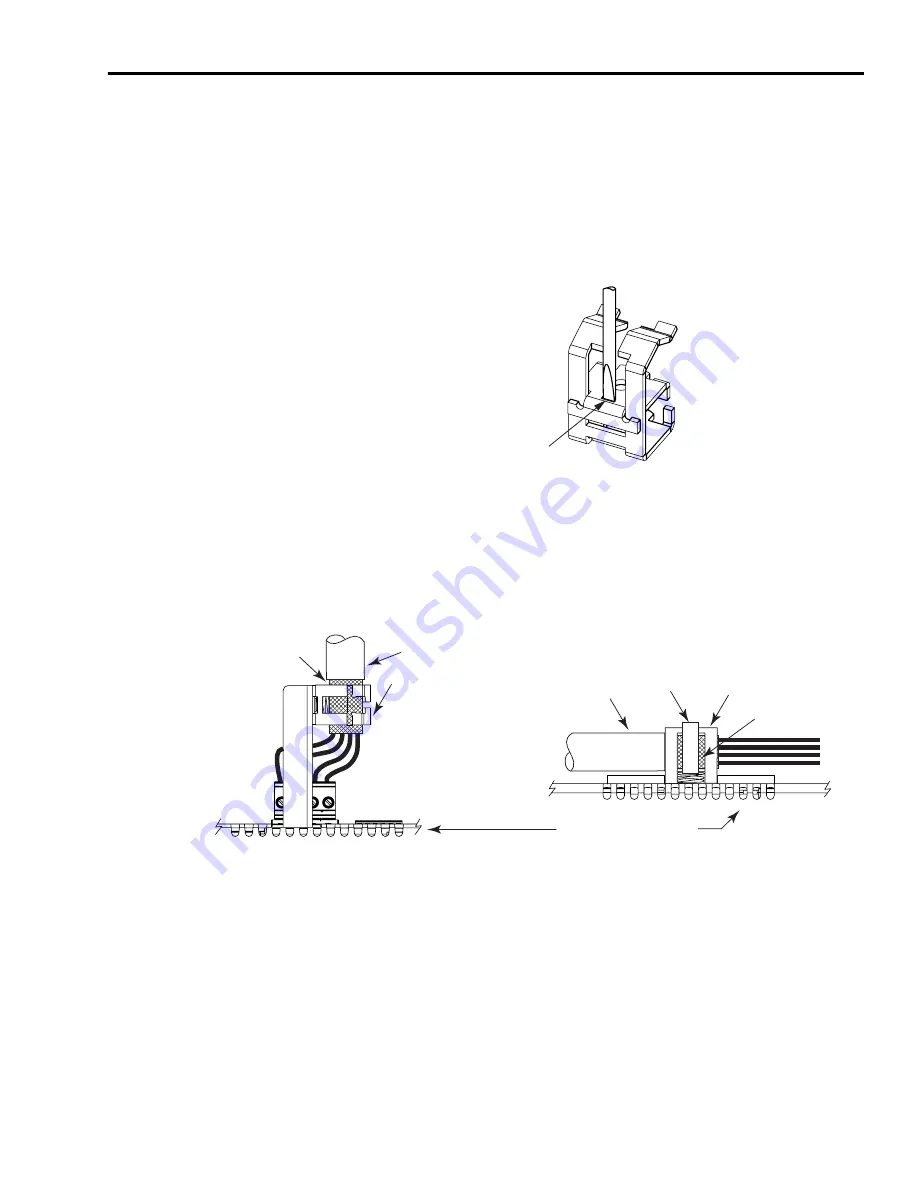
Applying the Motor Cable
Shield Clamp
This procedure assumes you have completed wiring your motor
power (MP) connector and are ready to apply the motor cable shield
clamp.
Follow these steps to apply the motor cable shield clamp.
1.
Use a small flat blade screwdriver to depress the spring loaded
clamping plate.
2.
Position the exposed portion of the cable braid directly in line
with the clamp.
3.
Release the spring, making sure the cable and cable braid are held
secure by the clamp.
4.
Attach tie wrap around cable and clamp for additional strain relief.
5.
Repeat Steps 1...4 for each AM and IAM.
Flat Blade Screwdriver
3.5 mm (0.14 in.) tip
Cable Clamp
Screwdriver
tip in slot
Tie Wrap
Outer Insulation
Motor Cable
Exposed Braid
(under clamp)
Cable Clamp
Vent holes on top of IAM/AM
Motor
Cable
Exposed Braid
(under clamp)
Cable Clamp
Outer Insulation
Horizontal Cable Clamp Orientation Example
Vertical Cable Clamp
Orientation Example
Содержание Allen-Bradley Kinetix 6000
Страница 8: ...Publication 2094 UM001A EN P September 2006 8 Table of Contents...
Страница 18: ...Publication 2094 UM001A EN P September 2006 18 Start...
Страница 118: ...Publication 2094 UM001A EN P September 2006 118 Connecting the Kinetix 6000 Drive System...
Страница 144: ...Publication 2094 UM001A EN P September 2006 144 Configure and Startup the Kinetix 6000 Drive System...
Страница 168: ...Publication 2094 UM001A EN P September 2006 168 Removing and Replacing the Kinetix 6000 Drive Modules...
Страница 190: ...Publication 2094 UM001A EN P September 2006 190 Specifications and Dimensions...
Страница 256: ...Publication 2094 UM001A EN P September 2006 256 Integrating Resistive Brake Modules with Kinetix 6000 Drives...
Страница 265: ...Publication 2094 UM001A EN P September 2006 265 Notes...
Страница 266: ...Publication 2094 UM001A EN P September 2006 266 Notes...
Страница 267: ...Publication 2094 UM001A EN P September 2006 267 Notes...


