Publication 700-AT001A-EN-E June 2002
Q & A
4-5
What Is the Difference
Between Recommended
Values and Rated Values?
The maximum load current of an SSR is determined on the
assumption that the SSR is used independently connected to a
resistive load.
A 20 to 30% safety margin will be required if an inductive load, such
as a transformer or motor, is used due to the inrush current that will
flow. Refer to Appendix A, page 6-1 .
What Is
Counter-electromotive
Force?
Counter-electromotive force is generated from a DC inductive load
when the load coil is turned OFF.
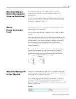
As shown below, magnetic flux is generated when voltage is applied
to a coil.
When the switch is turned OFF, the magnetic flux will disappear. Due
to the self-induction of the coil, counter-electromotive force voltage
will be generated in the direction required to maintain the magnetic
flux even though the switch is already closed. Therefore, the
counter-electromotive force has no way to escape, and a very high
voltage is generated.
The counter-electromotive force may cause contact friction damage
and fatal element damage. Pay utmost attention when using DC
inductive loads. As shown below, the power supply voltage and
counter-electromotive force will be imposed on the closed switch.
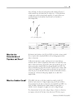
Refer to page 2-6 “DC ON/OFF Noise Surges.”
What Is the Meaning of
I
2
t
for Fuse Selection?
When a fuse is connected to an SSR, the
I
2
t of the SSR is the integral
value of an inrush current that flows for a specified time from the fuse
into the SSR when the SSR is turned ON.
The following table provides examples of permissible
I
2
t values for
the respective SSRs. When using a high-speed breaking fuse for an
SSR, check in pub. 700-SG003B-EN-P that the
I
2
t is the same as or less
than the specified value.
I
2
t Values
$UFJHQHUDWLRQ
&DW1R
9DOXH
6+B
$
V


