background image

46

Rockwell Automation Publication 6181X-UM002A-EN-P - October 2017

Chapter 5

Set Up the UEFI Utility

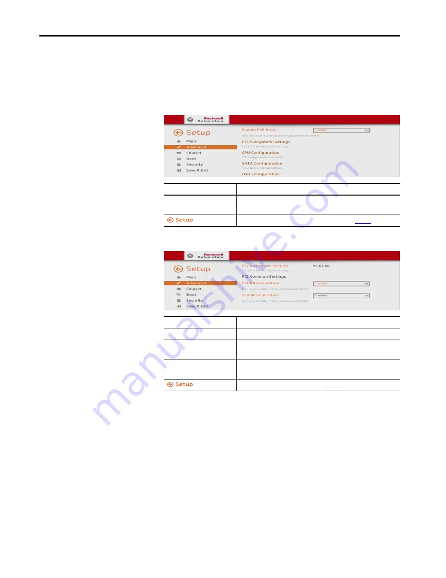
Advanced

Enable PXE Boot

When PXE boot is enabled, a computer boots from a server on a network 
before it boots the operating system on the local storage drive.

PCI Subsystem Settings

Parameter

Description

Enable PXE Boot

Enables or disables boot option for legacy network devices. 
Options: Enabled or Disabled (default)

Returns you to Firmware Configuration set-up screen; see 

page


4

6

.

Parameter

Description

PCI Bus Driver Version

Displays the PCI bus driver version information.

PERR# Generation

Enables or disables PCI Device to Generate PERR#.
Options: Enabled or Disabled (default)

SERR# Generation

Enables or disables PCI Device to Generate SERR#.
Options: Enabled or Disabled (default)

Returns you to the main set-up screen; see 

page 42

.

Содержание Allen-Bradley 6181X-12A2SW71DC, Allen-Bradley 6181X-00N2SW71DC, Allen-Bradley 6181X-12A2SWX1DC, Allen-Bradley 6181X-00N2SWX1DC,

Страница 1: ...81X 12A2SW71DC 6181X 00N2SW71DC 6181X 12A2SWX1DC 6181X 00N2SWX1DC 6189X MCLPS 6189X 8GDDR3 6189X 16GDDR3 6189V CFSSD8GB 6189V CFSSD16GB 6189X 128GBSSD 6189X 256GBSSD User Manual OriginalInstructions Для заказов 7 499 707 11 20 Email i sp t ru 8 800 511 65 88 Бесплатно по РФ ...

Страница 2: ...information circuits equipment or software described in this manual Reproduction of the contents of this manual in whole or in part without written permission of Rockwell Automation Inc is prohibited Throughout this manual when necessary we use notes to make you aware of safety considerations Labels may also be on or inside the equipment to provide specific precautions WARNING Identifies informati...

Страница 3: ...ation 15 Hazardous Locations 16 Hot Surfaces 17 Restricted Access Location 17 Environnements Dangereux 18 Installation Guidelines 19 Mounting Clearance Requirements 20 Computer Dimensions 21 Tools for Computer Installation 22 Install the Computer 22 Panel Mounting Guidelines 22 Panel Cutout Dimensions 22 Mount the Display Computer in a Panel 23 Mount the Non display Computer on a Wall 24 Connect P...

Страница 4: ... Card 36 Install an Add in Card 37 Replace or Add Memory Modules 38 Memory Configuration Guidelines 38 Replace or Add a Memory Module 39 Real time Clock RTC Battery 39 Chapter5 Set Up the UEFI Utility Set up Utility Overview 41 Access the Set up Utility 42 Set up Screen Overview 42 Firmware Update 43 Firmware Configuration 44 Main 45 Advanced 46 Chipset 51 Boot 52 Security 53 Save and Exit 53 Diag...

Страница 5: ...ar the CMOS 70 Ship or Transport the Computer 71 Dispose of the Computer 71 Chapter7 Use a Touch Screen Touch Screen Technology 73 Driver Software 73 Resistive Touch Screen Technology 73 Calibrate the Touch Screen 74 Chapter8 Maintain the Computer Clean the Computer 75 Clean the Integrated Display 75 Clean the Heat Sink and Vent Holes 75 Remove Paint and Grease from the Bezel 76 RTC Battery 76 Ind...

Страница 6: ...6 Rockwell Automation Publication 6181X UM002A EN P October 2017 Table of Contents Notes ...

Страница 7: ...interconnect COM Communication serial port interface PCIe Peripheral component interconnect express DDR Double data rate RAM PELV Protective extra low voltage DIMM Dual in line memory module POST Power on self test DP DisplayPort digital display interface RAM Random access memory DVI Digital video interface RTC Real time clock EEA European Environment Agency SELV Safety extra low voltage EMC Elect...

Страница 8: ...kwell Automation sales representative Resource Description Industrial Computer and Monitor Specifications Technical Data publication IC TD001 Provides technical specifications for the 6181X integrated display and non display computers for hazardous locations 6181X Industrial Computers for Hazardous Locations Series H Installation Instructions publication 6181X IN002 Provides procedures to install ...

Страница 9: ...nd Download Center PCDC at http compatibility rockwellautomation com Pages home aspx Computer Options Table 1 summarizes the options that are available for industrial computers for hazardous locations Table 1 Computer Options Topic Page Operating Systems 9 Computer Options 9 Computer Nameplate Information 10 Hardware Features 11 Cat No Model Series Display Size Touch Screen Windows OS 6181X 00N2SW...

Страница 10: ...nformation The computer catalog number serial number and date code are on its nameplate Record the following information in this table for future reference Cat No Description 6189X MCLPS Replacement mounting clips 10 6189X 8GDDR3 8 GB DDR3 RAM memory for extended temperature 6189X 16GDDR3 16 GB DDR3 RAM memory for extended temperature 6189V CFSSD8GB CompactFlash card 8 GB single level cell SLC sol...

Страница 11: ...el 5 Serial COM ports RS 232 2 10 Functional ground screw 2 128 GB MLC SSD 6 1 Gb LAN ports RJ45 2 11 USB 3 0 ports 4 1 3 Rear cover 7 PCIe riser slot cover 12 DVI D port 4 CompactFlash CF Type II card slot 1 8 Power switch 13 DisplayPort 9 DC input terminal block 1 The USB ports and the bottom CF card slot are hot swappable but only in non hazardous locations For more information about proper use...

Страница 12: ...12 Rockwell Automation Publication 6181X UM002A EN P October 2017 Chapter 1 Features Notes ...

Страница 13: ...for service Parts List The computers ship with these items Topic Page Before You Begin 13 Parts List 13 Installation Precautions 14 Environnements Dangereux 18 Installation Guidelines 19 Mounting Clearance Requirements 20 Computer Dimensions 21 Tools for Computer Installation 22 Install the Computer 22 Connect Power 25 Connect to a Network 26 Item Description Hardware Screws with grommets to mount...

Страница 14: ...turbance This equipment is supplied as an open type equipment To meet some regulatoryrequirements thecomputermustbemountedinanenclosurethatis suitably designed for environmental conditions that can be present and appropriately designed to help prevent personal injury resulting from accessibilitytoliveparts Theinterioroftheenclosuremustbeaccessibleonlyby using a tool All 6181X 12 display computers ...

Страница 15: ...adiation and greatly increase its field life If you install a sun shield that closes over the display the temperature between the sun shield and the display cannot exceed the maximum temperature of the display which is 55 C 131 F Adequately ventilate all sun shields to help prevent excess heat rise on the computer display Use stirring fans or active cooling in high altitude and high ambient temper...

Страница 16: ...upply terminals to the equipment The USB ports have not been evaluated as nonincendive field wiring The internal enclosure ambient temperature range is 20 70 C 4 158 F 2 The following applies only to display models 6181X 12A2SW71DC and 6181X 12A2SWX1DC The equipment shall only be used in an area of not more than pollution degree 2 as defined in EN IEC 60664 1 For EPL Gc the equipment shall be inst...

Страница 17: ...ce with the authority having jurisdiction In Canada all wiring must be in accordance with Section 18 1J2 of the Canadian Electrical Code and in accordance with the authority having jurisdiction For European Zone 2 and IECEx applications Transient protection shall be provided that is set at a level not exceeding140 ofthepeakratedvoltagevalueatthesupplyterminals to the equipment Non displaycomputers...

Страница 18: ...ont la température d inflammabilité est inférieure à 135 C ATTENTION This page is a French translation of portions of the Hazardous Locations section to comply with certification agency requirements ATTENTION Danger d explosion La substitution de composants peut rendre cet équipement impropre à une utilisation en environnement dangereux Ne pas déconnecter l équipementsans s être assuré que l alime...

Страница 19: ...ide 20 70 C 4 158 F back side Consider a user supplied fan heat exchanger or air conditioner for heat that is generated by other devices in the enclosure The relative humidity of the ambient air must be between 10 90 and must avoid condensation The enclosure or cover must always remain in place during operation The cover provides protection against high voltages inside the computer and inhibits ra...

Страница 20: ...n enclosure by using the minimum clearances unless adequate ventilation or other methods are used to lower the temperature within the enclosure Allowenoughclearancetoinstallorremoveperipheralcomponents suchas internal drives The minimum required enclosure size HxWxD is 403 x 497 x 154 mm 15 87 x 19 57 x 6 06 in Right and left are based on facing a computer from inside an enclosure Item Description...

Страница 21: ...e necessary for computer installation Figure 3 Non display Computers Figure 4 Integrated Display Computers 1 6 0 06 190 5 7 5 83 4 3 28 57 5 2 26 335 3 13 2 320 2 12 61 238 2 9 37 16 4 0 65 16 4 0 65 87 1 3 43 87 1 3 43 87 1 3 43 251 9 88 Dimensions are in mm in 115 4 53 349 13 74 101 3 4 75 4 2 97 14 5 0 57 320 12 6 251 9 88 279 10 98 115 4 53 Dimensions are in mm in ...

Страница 22: ...nting Clearance Requirements on page 20 Cut support panels to specifications before installation Take precautions so metal cuttings do not enter components that are already installed in the panel Support panels must be at least 16 gauge for proper sealing against water and dust and to provide proper support The supplied mounting hardware accommodates panel thickness between 16 6 gauge or 1 6 6 mm ...

Страница 23: ... 5 Place the computer in the panel cutout 6 Slide the clips into the holes on the top bottom and sides of the computer 7 Hand tighten the clips around the bezel by following this tightening sequence 8 Repeat this process at least three times until the clips are hand tight and the gasket is compressed uniformly against the panel 9 Tighten the clips to a torque of 1 35 N m 12 lb in by following the ...

Страница 24: ...four supplied M4 panhead screws The illustration shows the mounting hole locations with dimensions in mm in 3 Attach two of the supplied screws with grommets to positions 1 and 2 4 Mount the computer to the wall 5 Attach the remaining two supplied screws with grommets to positions 3 and 4 6 Tighten to a torque that is appropriate for the screw and wall material The recommended torque in steel is 1...

Страница 25: ...ou connect power to the computer for the first time these actions occur The default BIOS setting automatically starts the computer after it is plugged into a power source YoumustreadandacceptanEndUserSetupprocedureforcomputerswitha Windows operating system Do not disconnect power from the system until after the Windows Setup procedure is completed Disconnected power during this procedure can resul...

Страница 26: ...r external wire Use a ground wire with an insulation color allowed by local inspection authority Ring Connector Functional Ground Screw WARNING When you connect a LAN cable verify that the cable is fully inserted in the LAN port and the latch is engaged Failure to do so can result in an electrical arc that can cause an explosion in a hazardous location IMPORTANT To help prevent performance degrada...

Страница 27: ...ne maintenance Always use the proper power down procedures as required by your operating system such as the Shut Down command in the Microsoft Windows operating system After you shut down the computer do not apply power again until shutdown is complete Topic Page Operating Guidelines 27 Touch ScreenPrecautions 28 Start the Computer 28 Restart the Computer 29 Shut Down the Computer 29 Adjust the Di...

Страница 28: ...lttoreadanduseofthisscreencouldresult in a potentially hazardous outcome Do not use the LCD touch screen under these circumstances System design must take into account that the LCD screen or LCD touch screen can lose functionality and therefore be unable to maintain or change control of the system The touch screen cannot be the single point of control of critical functions and is not intended to r...

Страница 29: ...ers have an adjustable display brightness setting that can be adjusted in the BIOS The default setting is 70 Follow these steps to adjust the display brightness 1 Restart the computer as detailed in Restart the Computer on page 29 2 During POST press F2 to access the BIOS set up utility 3 Use the BIOS set up utility to adjust the display brightness Method Actions Windows OS With an attached keyboa...

Страница 30: ...30 Rockwell Automation Publication 6181X UM002A EN P October 2017 Chapter 3 Operate the Computer Notes ...

Страница 31: ...ltages Disconnect all power to the computer before you install or remove components Topic Page Accessories and Replacement Parts 31 Voltage Precautions 31 Electrostatic Discharge Precautions 32 Pre configuration 32 Post configuration 33 Tools for Component Replacement 33 Remove the Cover 33 Reinstall the Cover 34 Replace a Solid state Drive 35 Load a CompactFlash Card 36 Install an Add in Card 37 ...

Страница 32: ...place it with the assembly side down Pre configuration Follow these steps before you remove the cover or replace a hardware component 1 Shut down the computer and all peripherals that are connected to it 2 Disconnect all cables from power outlets to avoid exposure to high energy levels If necessary label each cable to expedite reassembly 3 Disconnect telecommunication cables to avoid exposure to a...

Страница 33: ...es and power to the computer 6 Press the power switch to start the computer Tools for Component Replacement The following tools are required for component replacement 2 cross head screwdriver Anti static wriststrap Remove the Cover To install replace or upgrade internal computer components you must first remove the cover Follow these steps to remove the rear cover the display computer is shown 1 F...

Страница 34: ... Follow these steps to reinstall the rear cover the display computer is shown 1 Follow steps 1 3 for Post configuration on page 33 2 Reattach the rear cover to the chassis A 3 Close the cover B 4 Tighten the three screws to secure the rear cover C 5 Follow steps 5 and 6 for Post configuration on page 33 C B C C A A ...

Страница 35: ...e screw that secures the slot cover of the drive bay H 10 Follow the steps for Post configuration on page 33 WARNING The solid state drive SSD bay on the side of all computer models is not hot swappable You must first shut down the computer before you can insert or remove a SSD tray from this bay Do not connect or disconnect components unless power has been switched off and the area is known to be...

Страница 36: ...mponents unless power has been switched off and the area is known to be non hazardous WARNING Use only catalog numbers 6189V CFSSD8GB and 6189V CFSSD16GB CF cards in the 6181X computers for hazardous locations Substitution of components can impair suitability for hazardous locations WARNING The CF card slot on the bottom side of all computer models is hot swappable but only in a non hazardous loca...

Страница 37: ... See the documentation that came with the card 9 Reinstall the computer cover as detailed in Reinstall the Cover on page 34 IMPORTANT When used in hazardous locations the computer supports peripheral cards rated 4 W maximum and the add in cardmust be certified to UL Class I Division 2 Groups A B C D T4 or ATEX IECEx Zone 2 as applicable to the area of installation For ATEX and IECExapplications op...

Страница 38: ... with memory modules of the same capacity All 6181X computers ship with a dual memory module configuration WARNING Unless ordered differently 6181X computers ship with 8 GB of memory 2 x 4 GB If upgrading to 16 GB of memory 2 x 8 GB use only catalog number 6189X 16GDDR3 which is memory specifically for use in hazardous locations Other memory modules are not acceptable for use in hazardous location...

Страница 39: ...atic bag b Orient the module so the notch on its bottom edge aligns with the keyed surface of the DIMM slot See Figure 5 on page 38 c Press the module fully into the slot to engage the lock levers See Figure 5 on page 38 6 Reinstall the computer cover as detailed in Reinstall the Cover on page 34 7 Follow the steps for Post configuration on page 33 Real time Clock RTC Battery This computer contain...

Страница 40: ...40 Rockwell Automation Publication 6181X UM002A EN P October 2017 Chapter 4 Replace Components Notes ...

Страница 41: ...ever you can run the set up utility to do the following Change the system configuration Change the UEFI setup when a configuration error is detected by the system Redefine communication ports to prevent any conflicts Read the current amount of system memory Change the boot drive order Set or change the password or make other changes to the security settings Upgrade the system firmware Run the diag...

Страница 42: ...nterface On the left are six menu buttons that are stacked vertically Each menu button provides access to information commands or configurable options for the following topics Firmware Update Firmware Configuration Diagnostics AMI Rescue Hardware History Exit Press Result F2 Accesses a graphical interface of set up environment IMPORTANT Screen shots in this chapterare from the UEFI graphical inter...

Страница 43: ...reen appears 2 Click Browse to locate the firmware file 3 Click Flash Parameter Description Browse Click to navigate to the firmware file saved onto a media Firmware file location Select or type the file name for the firmware file Flash Click to start the BIOS programming IMPORTANT The USB mass storage device that contains the firmware file must be FAT FAT16 or FAT32 formatted to be recognized See...

Страница 44: ... Use this menu to view general computer information and for basic system configuration Advanced Use this menu to configure information for the PXE PCI ACPI processor SATA USB power video graphics super IO hardware monitor and AMT Chipset Use this menu to configure system chipset information Security Use this menu to set or change user and administrator passwords Boot Use this menu to configure boo...

Страница 45: ... installed memory System Date Set the system date Format Weekday MM DD YYYY Weekday Month Day Year System Time Set the system time Format HH MM SS Hour Minute Second Runtime Hours Records the total hours of computer runtime Manufacturer System manufacturer Catalog Number Allen Bradley catalog number with series letter WIN Number Warranty information number Version SYS System version manufacture da...

Страница 46: ...XE Boot Enables or disables boot option for legacy network devices Options Enabled or Disabled default Returns you to Firmware Configuration set up screen see page 46 Parameter Description PCI Bus Driver Version Displays the PCI bus driver version information PERR Generation Enables or disables PCI Device to Generate PERR Options Enabled or Disabled default SERR Generation Enables or disables PCI ...

Страница 47: ...t Displays 64 bit support status Hyper threading Enables or disablesthe hyper threading technology Options Enabled default or Disabled Intel Virtualization Technology VT x When enabled a Virtual Memory Manager VMM can use the extra hardware capabilities provided by Vanderpool Technology Options Enabled default or Disabled Intel Virtualization Technology for Directed I O VT d Enables or disables VT...

Страница 48: ...led Returns you to Firmware Configuration set up screen see page 46 Parameter Description USB Ports Enables or disables a USB port Options Enabled default or Disabled Ports 0 3 Bottom of computer see page 11 for port locations CF Card Reader internal see page 36 for CF card location IMPORTANT IfyoudisableaUSBport itreducesaccessriskfromunauthorized or malicious sources Returns you to Firmware Conf...

Страница 49: ...eter Description Serial Port Enables or disables the serial COM1 port Options Checked box enabled default or unchecked box disabled Device Settings Displays the Base I O address and IRQ setting of serial port 1 Change Settings Select an optimalsetting for the super I O device Options Auto default IO 3F8h IRQ 4 IO 2F8h IRQ 4 IO 3E8h IRQ 4 IO 2E8h IRQ 4 Parameter Description Serial Port Enables or d...

Страница 50: ...ofvarious hardware components All values are read only DIMM1 temperature DIMM2 temperature Vcore Temperature MB Temperature VCORE_S0_CPU V1D05_S0 V1D5_S0 V12D0_S0 VDDQ_S3_MEM V3D3_S0 V5D0_S0 VBAT CPU U6502 Max CPU U6502 Min DIMM1 U6503 Max DIMM1 U6503 Min DIMM2 U6504 Max DIMM2 U6504 Min Vcore U6507 Max Vcore U6507 Min MB U6506 Max MB U6506 Min Returns you to Firmware Configuration set up screen se...

Страница 51: ... Options Enabled default or Disabled Returns you to the main set up screen see page 42 Parameter Description BIOS Boot Time WatchDog Enables or disables BIOS boot timeout Options Enabled or Disabled default BIOS Timer Out value 1 1 This field is only visible when BIOS Boot time Watchdog is enabled Set BIOS timer timeout value 10 20 or 30 minutes 10 is default OS Time WatchDog Enables or disables O...

Страница 52: ...ables or disables Quiet Boot option Option Enabled or Disabled default IMPORTANT When enabled this option hides the POST screen messages at computer startup Boot Option Priorities Change the boot order By default these devices are the boot priority SSD USB bootable device PXE UEFI shell Follow instructions in the dialogbox to change the boot order and to enable or disable options Returns you to th...

Страница 53: ...uce assess risk from unauthorized or malicious sources IMPORTANT If you forget the user password there are two ways to reset it Remove and replace the battery see RTC Battery on page 76 Clear the UEFI see Clear the CMOS on page 70 Secure Boot Menu Customizable secure boot settings Disabled is the default setting Returns you to the main set up screen see page 42 Parameter Description Save Changes a...

Страница 54: ...ight arrow keys to toggle between the five Diagnostics menu selections The following table lists the shortcut options in the Diagnostics menu Button Description Esc Stops a test in progress or exits Diagnostics from any of the six menu options Enter Runs the highlighted test or option F1 Displays the Help screens F2 Edits batch parameters F3 Loads batch parameters F4 Saves batch parameters F5 Sele...

Страница 55: ...unction overwrites any data on the primary operating system partition on the internal drive IMPORTANT Thefollowinginstructionsareforthebuilt inbackupandrestoreutility AMI Rescue You can also use third party utility or software to create an image backup and restore System images are also available from the Rockwell Automation Product Compatibility and Download Center http compatibility rockwellauto...

Страница 56: ...ick Browse to locate the backup source The backup is automatically assigned a name based on the system date 4 Click Advanced to select the partitions to back up 5 Select all Disk 1 options so the entire OS image is backed up IMPORTANT Attach a FAT32 formatted USB storage device to the computer before you perform these steps Use a USB storage device appropriately sized for the amount of data being ...

Страница 57: ...it 11 Click Backup Now Restore OS Image From a Hidden Partition Perform the following steps to restore your computer to factory default settings 1 Click the AMI Rescue menu to access the AMI Restore screen 2 Click Restore from an Image IMPORTANT Do not select Recovery it is the factory OS image that you wish to back up IMPORTANT When you restore from a back up image all data on the target drive is...

Страница 58: ...f Image File field click Browse to locate the image source 4 From the List of Volumes menu select Recovery 5 Click Exit 6 In the Destination of Restore Data field click Browse to locate the destination source IMPORTANT Recovery is the default OS image source which is the hidden partition on your internal storage drive ...

Страница 59: ...ility Chapter 5 7 From the List of Labels menu select the default destination 8 Click Advanced 9 On the Select Partition screen select all boxes for Disk 0 so the entire OS image is restored 10 Click OK 11 Click Exit IMPORTANT The Label name is similar or identical to the above example ...

Страница 60: ...USB storage drive 1 Click the AMI Rescue menu to access the AMI Restore screen 2 Click Restore from an Image IMPORTANT The following warnings may appear If prompted click Yes to continue If prompted click Yes to continue If prompted click No to continue If prompted click Yes to continue IMPORTANT Toperformthesesteps youmustalreadyhaveabacked upOSimageonan external USB storage drive from Make a Bac...

Страница 61: ... of Image File field click Browse to locate the image source 4 From the List of Volumes menu select the USB storage drive 5 Click Exit 6 In the Destination of Restore Data field click Browse to locate the destination source IMPORTANT Do not select Recovery it is the OS image on the computer that you wish to restore ...

Страница 62: ...e 8 Click Advanced 9 On the Select Partition screen select all boxes for Disk 0 so the entire OS image is restored 10 Click OK 11 Click Exit IMPORTANT If no labels are visible then the backed up OS image folder mustbe moved to the root directory of the USB storage drive The backup is automatically assigned a name based on the system date such as 03172016_00 ...

Страница 63: ... Set Up the UEFI Utility Chapter 5 12 Click Restore Now to start the restoration process IMPORTANT The following warnings may appear If prompted click Yes to continue If prompted click Yes to continue If prompted click No to continue If prompted click Yes to continue ...

Страница 64: ...eratures in C over the entire runtime All displayed values are read only and the time stamp is 24 hour clock Menu Description CPU DIMM1 DIMM2 Vcore MB Same hardware temperatures as identified in Hardware Monitor for more information see page 50 Runtime Hours The total hours that the computer has been powered up IMPORTANT Make sure thatall writes to the drive are complete before you remove the driv...

Страница 65: ...Rockwell Automation Publication 6181X UM002A EN P October 2017 65 Set Up the UEFI Utility Chapter 5 Exit Use the Exit menu to close the UEFI set up utility ...

Страница 66: ...ellautomation com Pages home aspx 3 On the home page click Downloads 4 On the Find Downloads page use your computer model as the search criteria 5 Follow the instructions on the PCDC site to find your BIOS 6 Download the BIOS file to your USB flash drive 7 After the file downloads restart the computer 8 During POST press F5 9 Select Internal Shell 10 Wait for startup nsh to load 11 Follow the onsc...

Страница 67: ...See Shut Down the Computer on page 29 for more information 2 Apply power to the computer 3 During POST press F2 to access the UEFI set up utility 4 Select the Hardware Monitor menu from the Advanced menu Use this menu to determine if there is an issue with internal voltages or component temperatures See Hardware Monitor on page 50 for more information Topic Page Hardware Monitoring 67 Troubleshoot...

Страница 68: ...p process ends Diagnostics If you completed the troubleshooting steps and issues remain use the Diagnostics menu in the UEFI set up utility to isolate the issue Diagnostics tests computer components to determine the cause of a malfunction Press F2 during POST or press F10 at any time to access the UEFI set up utility F2 during POST accesses the main menu of the UEFI set up utility Select Diagnosti...

Страница 69: ...tinue and press Enter You do not need to disconnect or move your computer to perform an initial diagnosis The selected test affects the process which can take as little as 5 minutes or as long as 8 hours After Diagnostics has run you can generate a report for analysis by a technical support representative which expedites any necessary repair process Load the System Defaults If the computer fails a...

Страница 70: ...readable You cannot access the UEFI set up utility to load the system defaults Follow these steps to clear the CMOS 1 Back up all system data and then shut down the computer 2 Follow the steps for Pre configuration on page 32 3 Disconnect the power and peripheral cables from the computer 4 Remove the rear cover as detailed in Remove the Cover on page 33 5 Locate the CMOS header on the motherboard ...

Страница 71: ...ors contain heavy metals that can contaminate the earth Therefore check with local health and sanitation agencies for ways to properly dispose of computer equipment When a storage drive is part of what you are disposing then permanently erase any data on it or destroy the drive before it is disposed IMPORTANT When you clear the CMOS all UEFI settings return to their defaults UEFIsettingsotherthand...

Страница 72: ...72 Rockwell Automation Publication 6181X UM002A EN P October 2017 Chapter 6 Troubleshoot the System Notes ...

Страница 73: ...ion com Pages home aspx Resistive Touch Screen Technology Resistive touch screens are activated when you apply pressure to the touch screen with your finger You can operate a resistive touch screen while gloves are worn Topic Page Touch Screen Technology 73 Driver Software 73 Resistive Touch Screen Technology 73 Calibrate the Touch Screen 74 TIP If you must reinstall the touch screen driver the to...

Страница 74: ...the computer is installed and calibrated at the factory Perform the following steps to recalibrate the touch screen 1 Run the configuration utility for the touch screen Access the utility through the Programs menu of the operating system 2 Start the calibration routine that is offered within the utility 3 Follow the calibration instructions on the touch screen ...

Страница 75: ...t cloth 3 Dry the display with a chamois or moist cellulose sponge to avoid water spots Clean the Heat Sink and Vent Holes Follow these steps to clean the chassis 1 Disconnect power from the computer at the power source 2 Disconnect all peripheral devices from the computer 3 Vacuum dust and debris from the heat sink and vent holes Topic Page Clean the Computer 75 RTC Battery 76 ATTENTION If the co...

Страница 76: ... Battery This computer contains a lithium battery that you cannot replace Return the computer to Rockwell Automation for battery replacement For return information contact your local distributor or Rockwell Automation representative or visit http www rockwellautomation com services online phone ATTENTION Verify that isopropyl alcohol does not come in contact with the equipment labels Alcohol can c...

Страница 77: ...2 DIMM slots install memory 39 display cleaning precautions 75 E European Union directive compliance 14 F Firmware Configuration Advanced 46 Boot 52 Chipset 51 Main 45 Save Exit 53 Security 53 H hardware features 11 hardware diagnostics 67 hardware monitor 67 hazardous locations 16 hot surfaces 17 restricted access 17 safety guidelines 35 36 hot surfaces 17 I installation 13 27 apply power 25 guid...

Страница 78: ...splay 34 remove performance non display 33 replace components post configuration procedure 33 pre configuration procedure 32 replacement parts 31 restricted access 17 S Setup menu AMI Rescue 55 Diagnostics 54 Exit 65 Firmware Configuration 44 Firmware Update 43 system defaults 69 turn on 28 T touch screen calibrating 74 type 73 touchscreen driver software 73 troubleshooting diagnostic utility 68 h...

Отзывы: