Installation and Wiring
2-3
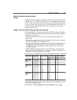
Terminal Block Wiring
Terminal Block Wiring Detail
Figure 2.2
Specifications
Terminal Block TB1 and TB2 Wiring Specifications
Table 2.A
➊
For single phase input applications, connect the AC input power to input terminals S (L2) and T (L3).
➋
See Table 2.B for minimum recommended branch circuit protective devices.
➌
Bulletin 160 Drives are UL Listed (see Appendix A for details) as motor overload protective devices
(IEC Class 10 overload). An external overload relay is not required for single motor applications
as long as the Drive kW (HP) rating is less than three times larger than the motor kW (HP) rating.
➍
Each terminal supports up to 2 wires of approved gauge.
Model
Screw Size
Max./Min. Wire Size
➍
mm
2
(AWG)
Max./Min. Torque
Nm (lb.-in.)
4.0 kW (5 HP)
M4
5.26 – 3.31 (10 – 12)
1.35 – 0.90 (12 – 8)
All Other Ratings
M4
3.31 – 0.82 (12 – 18)
1.35 – 0.90 (12 – 8)
Required Branch
Circuit Disconnect
➊
Branch Circuit
Protective Device
➋
BR+
T/L3
S/L2
R/L1
BR–
DC+
W/T3
V/T2
U/T1
DC–
Ground Terminal/Protective Earth
Terminal Block TB1
Terminal Block TB2
Motor
➌
Содержание Allen-Bradley 160 SSC Series
Страница 12: ...1 6 Getting Started End of Chapter ...
Страница 58: ...5 20 Parameters and Programming End of Chapter ...
Страница 66: ...A 4 Specifications End of Chapter ...
Страница 75: ...Accessories and Dimensions B 9 Drilling Template A Figure B 10 ...
Страница 76: ...B 10 Accessories and Dimensions Drilling Template B Figure B 11 ...
Страница 82: ...C 6 CE Conformity End of Chapter ...
Страница 87: ......

