background image

Rockwell Automation Publication 6181P-UM003A-EN-P - May 2014

109

Specifications

Appendix A

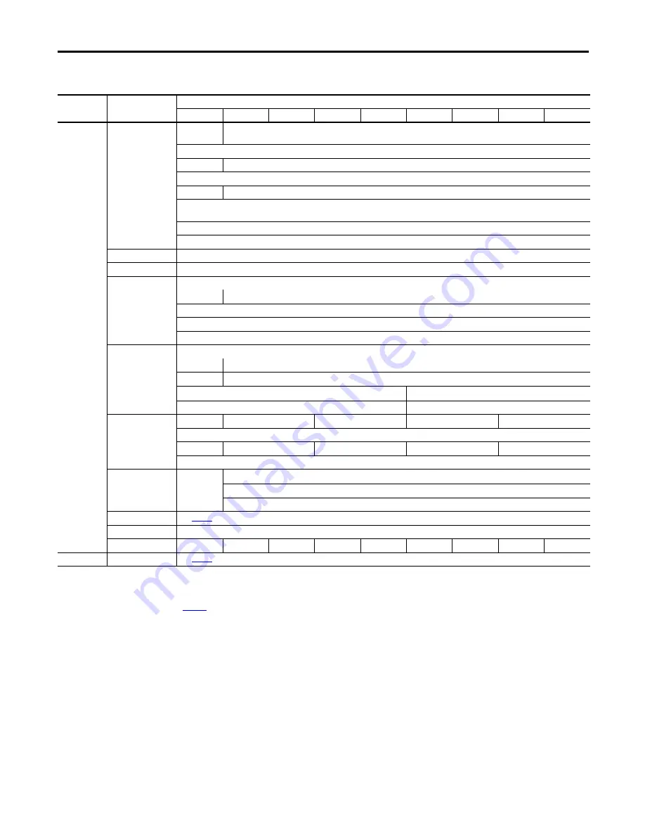
Table 12 - 1900P (19-inch display) Model Hardware and Software Specifications 

(continued)

Cat. No. 6181P-

Specifications

Attribute

19C2SW71DC

19A3HW71AC

19A3HW71DC

19A3SW71AC

19A3SW71DC

19B3HW71AC

19B3HW71DC

19B3SW71AC

19B3SW71DC

Hardware

Processor

Intel i3-
4102E

(2)

(2) 2 cores; 1.6 GHz; 3 MB cache; TDP 25W.

Intel i7-4700EQ; 4 cores; 2.4 GHz; 6 MB cache; TDP 47W

Hyperthreading

Yes

Turboboost

No

2.0

UEFI version

2.3.1

Intel AMT

None

9.0

Intel Rapid Start 
Capable

Yes

(3)

(3) Disabled by default.

Chipset

QM87 PCH

Video resolution 

1920 x 1200 at 60 Hz, max

Ethernet LAN 

10/100/1000 Mbps, 2 ports (rear); Intel i217LM (LAN1, with AMT) and Intel i210AT (LAN2)

Expansion slot 

1 PCI-express x8

(4)

(4) Configuration supplied with computer; se

page 114

 for other card configurations.

System memory 

Supplied

4 GB (2 x 2 GB)

8 GB (2 x 4 GB)

Maximum

16 GB (2 x 8 GB)

Memory type

DDR3-1600 204 pin SO-DIMM

Memory slots

2

Display (19 in.)

Bezel

Stainless steel

Aluminum

Touchscreen

Resistive

PCAP

Resolution (max)

SXGA 1280 x 1024

HD 1366 x 768

Aspect ratio

5:4

16:9

Supplied drive

(1)

(1) All drives are in a removable drawer.

SSD

HDD

SSD

HDD

SSD

Quantity

1

Size (min/each)

32 GB, 2.5 in.

100 GB, 2.5 in.

32 GB, 2.5 in.

100 GB, 2.5 in.

32 GB, 2.5 in.

Interface/location

SATA 0

ODD

None supplied

DVD-RW/CD-RW

Quantity

1

Interface/location

SATA 1

I/O ports

See 

page 14

.

CompactFlash

Type II slot with cover

Power supply

18-32V DC

120-240V AC

18-32V DC

120-240V AC

18-32V DC

120-240V AC

18-32V DC

120-240V AC

18-32V DC

Software

Windows OS

See 

page 10

.

Содержание 6181P

Страница 1: ...umbers 6181P 6189V 6181TRAY 6189V 6181HDD100GB 6189V 6181SSD32GB 6189V 6181SSD64GB 6189V BOOKBRKT 6189V DPDVI 6189V DPVGA 6189V PCIR 6189V EXTPCI2 6189V PSU6181AC 6189V PSU6181DC 6189V 8GSODDR3 6189V 16GSODDR3 6189V ODD 6189V ACCESSBOX6181 User Manual ...

Страница 2: ...l in whole or in part without written permission of Rockwell Automation Inc is prohibited Throughout this manual when necessary we use notes to make you aware of safety considerations Labels may also be on or inside the equipment to provide specific precautions Allen Bradley Rockwell Software and Rockwell Automation are trademarks of Rockwell Automation Inc Trademarks not belonging to Rockwell Aut...

Страница 3: ... UIB 17 Hardware Monitor and Watchdog Timer Utilities 18 Hardware Monitor 18 Watchdog Timer 18 Intel Active Management Technology AMT 9 0 18 Intel Rapid Start Technology 19 Chapter2 Installation Chapter Objectives 21 Installation Precautions 22 Environment and Enclosure Information 22 European Union Directive 22 Installation Guidelines 23 Mounting Clearance Requirements 24 Computer Dimensions 24 R...

Страница 4: ...eplacement Parts 43 Voltage Precautions 43 Electrostatic Discharge Precautions 44 Pre configuration 44 Post configuration 45 Required Tools 45 Remove the Cover 45 Reinstall the Cover 46 CompactFlash Card 46 Drive Precautions 47 Replace a Drive 47 Replace or Add Memory Modules 48 Memory Configuration Guidelines 49 Replace or Add a Memory Module 49 Replace the RTC Battery 50 Replace the Power Supply...

Страница 5: ...pset 75 User Interface Button UIB 76 Watchdog Timer 77 Boot 78 Security 79 Save Exit 80 Diagnostics 81 AMI Rescue 83 Make a Backup 85 Restore from an Image 86 Hardware History 87 Exit 88 Chapter6 SystemTroubleshooting Chapter Objectives 89 Hardware Monitoring 89 Troubleshooting 90 Troubleshooting Checklists 91 Issues during Startup 91 Issues after Startup 91 Issues Running New Software 92 Issues w...

Страница 6: ...hscreen 98 Chapter8 Maintenance Chapter Objectives 99 Clean the Computer 99 Clean the Integrated Display 99 Clean the Fan Intel Core i7 models 100 Clean the Heat Sink and Vent Holes 100 Remove Paint and Grease from Bezel 100 AppendixA Specifications 101 AppendixB AccessoriesInstallation Objectives 113 Pre installation Checklist 113 Install an Add in Card 114 PCI PCIe Riser Board Options 116 Instal...

Страница 7: ...e documents contain additional information to related products from Rockwell Automation You can view or download publications at http www rockwellautomation com literature To order paper copies of technical documentation contact your local Allen Bradley distributor or Rockwell Automation sales representative Resource Description Industrial Integrated Display Computers Product Information publicati...

Страница 8: ...play interface PXE Pre boot execution environment DVI Digital video interface RAID Redundant array of independent disks DVMT Dynamic video memory technology RAM Random access memory ECC Error correcting code RIUP Removeor insert under power eDP Embedded DisplayPort RMS Root mean square EEA European Environment Agency RTC Real time clock EMC Electromagnetic compatibility SAS Serial attached SCSI EO...

Страница 9: ...nd non display models are available with display sizes offered in both standard 4 3 5 4 format and widescreen 16 9 format 6181P stainless steel bezel display computers address NEMA 4X requirements and are a choice selection for food and beverage applications Various mounting methods are possible with these computers in landscape and portrait orientations as well as a space saving bookshelf mountin...

Страница 10: ...rating system updates have been applied to the factory image beyond the above listed service packs To obtain a copy of a factory system image contact your local technical support center or access the Rockwell Automation Product Compatibility and Download Center PCDC http www rockwellautomation com support pcdc page IMPORTANT 6181P computers do not ship with the Windows XP Professional operating sy...

Страница 11: ...t SP1 00N2SE71DC DC 00N3HW71AC 3 AC HDD 7 Professional 64 bit SP1 00N3HW71DC DC 00N3SW71AC AC SSD 00N3SW71DC DC 00N3RS81AC AC HDD 2 Server 2008 R2 64 bit SP 1 00N3RS81DC DC 12A2HW71AC 1200P 2 AC 12 4 3 Resistive Aluminum HDD 7 Professional 64 bit SP1 12A2HW71DC DC 12A2SW71AC AC SSD 12A2SW71DC DC 12A2SE71AC AC WES 7 64 bit SP1 12A2SE71DC DC 15A2HW71AC 1500P 2 AC 15 4 3 Resistive Aluminum HDD 7 Prof...

Страница 12: ...sional 64 bit SP1 17C2HW71DC DC 17C2SW71AC AC SSD 17C2SW71DC DC 17A3HW71AC 3 AC PCAP Aluminum HDD 17A3HW71DC DC 17A3SW71AC AC SSD 17A3SW71DC DC 19A2HW71AC 1900P 2 AC 19 5 4 Resistive Aluminum HDD 7 Professional 64 bit SP1 19A2HW71DC DC 19A2SW71AC AC SSD 19A2SW71DC DC 19A2SE71AC AC WES 7 64 bit SP1 19A2SE71DC DC 19C2HW71AC AC Stainless steel HDD 7 Professional 64 bit SP1 19C2HW71DC DC 19C2SW71AC AC...

Страница 13: ...els 4 3 and 5 4 aspect ratios publication 6181P DS002 1 6181P and 6181X Industrial Computers Cutout Template for Widescreen Display Models 16 9 aspect ratio publication 6181P DS003 1 Production test report Item Component Item Component Item Component 1 Mounting hole 4 8 Audio line in jack 15 Power input AC or DC 2 2 HDD or SSD 9 DisplayPort connector 16 Functional ground screw 3 Drive bay 1 10 Ser...

Страница 14: ... DVI I port 21 Rear cover 6 HDD or SSD 14 PCIe x8 riser slot cover 22 Microphone in jack 7 Mounting slots 15 Power switch 23 PS 2 keyboard port 8 Audio line in jack 16 Power input AC or DC 4 24 PS 2 mouse port 1 See Appendix A for touchscreen options 2 Available only on display models with aluminum bezel 3 An ODD is not available on all display models SeeAppendix A for further information 4 Model ...

Страница 15: ...tor 2 Mini SATA cable connector 2 11 Riser card board connector 21 Microphone in jack 3 eDP signal cable connector 12 Battery socket 22 PS 2 keyboard port 4 Panel cable connector 13 1 Gb LAN 2 port 23 Audio line out jack 5 Power switch cable connector 14 1 Gb LAN 1 port 24 PS 2 mouse port 6 USB cable connector 15 DVI Iport 25 Audio line in jack 7 ODD and HDD power cable connector 16 RearUSB 3 0 po...

Страница 16: ...ns The multi touch technology provides up to two simultaneous touches and common gesturing such as flicking rotating and pinch to zoom when operating the touchscreen These touchscreens can also be operated with gloves PCAP touchscreens are pre calibrated at the factory so re calibration by the user is not necessary The touchscreen glass has an anti reflective coating which results in a visually ap...

Страница 17: ...to be any keystroke up to three keystrokes in the OS or can be disabled all together Configuration of this button is done in the BIOS UEFI See User Interface Button UIB on page 76 for more information on configuring the UIB 4 3 2 1 Item Icon Indicator Status Description 1 System health status Red The computer s temperature threshold has been exceeded Off System health is normal 2 Drive access stat...

Страница 18: ...t logs created Watchdog Timer Watchdog timer is a utility that runs on the OS and watches the system If there is a program error or hardware malfunction that causes the OS to hang the watchdog timer times out and causes the system to automatically reboot An event log is created after the system restarts because the computer experienced an incorrect shutdown sequence This utility is beneficial for ...

Страница 19: ...for a quick resume into the OS from a deep sleep state in a matter of seconds For additional information on Intel Rapid Start visit http www intel com See Intel Rapid Start Technology on page 71 for more information on configuring Rapid Start IMPORTANT The SSD must first have a private partition allocated that is equal in size to the computer RAM ...

Страница 20: ...20 Rockwell Automation Publication 6181P UM003A EN P May 2014 Chapter 1 Features Notes ...

Страница 21: ...es information on the following topics Installation Precautions Installation Guidelines Mounting Clearance Requirements Computer Dimensions Required Tools Install the Computer Connect Peripherals Connect Power Functional Ground Screw Connect to a Network Review each mounting type and computer dimensions before installation ...

Страница 22: ...sure that is suitably designed for environmental conditions that can be present and appropriately designed to prevent personal injury resulting from accessibility to live parts The enclosure must be accessible only by using a tool All 6181P display computers are shipped with a gasketed bezel to meet specified NEMA UL Type and IEC IP ratingsonly when mounted ina panel or enclosure with an equivalen...

Страница 23: ...onditioner for heat generated by other devices in the enclosure The humidity of the ambient air must not exceed limits specified in Table 13 on page 110 and must avoid condensation The enclosure or cover must remain in place at all times during operation The cover provides protection against high voltages inside the computer and inhibits radio frequency emissions that can interfere with other equi...

Страница 24: ...learancesunlessadequateventilationorothercoolingmethodsare used to lower the temperature within the enclosure Allow enough clearance to easily install or remove internal drives optical discs cables and peripheral components Right and left are based on facing the front of the computer Item Description Value 1 Top 50 mm 2 in 2 Left for airflow 50 mm 2 in 3 Rear 50 mm 2 in 4 Right for airflow and dri...

Страница 25: ...rd Display Computer 115 4 53 349 13 74 103 4 06 72 2 83 14 5 0 57 320 12 60 115 4 53 279 10 98 251 9 88 145 5 71 408 9 16 1 28 1 1 320 12 6 33 4 1 31 15 8 0 62 33 4 1 31 145 5 71 14 5 0 57 103 4 06 15 8 0 62 251 9 88 309 12 16 IMPORTANT 1500P models with stainless steel bezels do not have the front USB port atright statusindicatorsintheupperright or the UIB below ...

Страница 26: ...uter 110 4 33 447 17 6 320 12 6 49 5 1 95 47 5 1 87 14 5 0 57 110 4 33 110 4 33 106 4 4 19 32 1 26 284 11 18 251 9 88 15 7 0 62 449 17 68 320 12 6 51 2 51 2 14 5 0 57 145 5 7 145 5 7 103 4 06 32 1 26 38 3 1 51 251 9 88 355 13 97 38 3 1 51 IMPORTANT 1700P models with stainless steel bezels do not have the front USB port at right status indicators in the upper right or the UIB below ...

Страница 27: ...2 1 26 320 12 6 63 3 2 5 63 3 2 5 54 75 2 16 14 5 0 57 54 75 2 16 120 4 72 120 4 72 120 4 72 106 4 4 19 251 9 88 399 3 15 72 IMPORTANT 1900P models with stainless steel bezels do not have the front USB port at right status indicators in the upper right or the UIB below 32 1 26 320 12 6 33 5 1 32 85 3 35 85 3 35 130 5 12 130 5 12 130 5 12 515 6 20 3 106 4 4 19 339 3 13 36 14 5 0 57 251 9 88 33 5 1 ...

Страница 28: ... For specific information refer to Mounting Clearance Requirements on page 24 Cut supporting panels to specifications before installation Take precautions so metal cuttings do not enter components already installed in panel Supporting panels must be at least 14 gauge for proper sealing against water and dust and to provide proper support The mounting hardware supplied accommodates panel thickness ...

Страница 29: ...tandard display models 4 3 and 5 4 aspect ratios 6181P Integrated Display Industrial Computers Cutout Template publication 6181P DS003 is included with widescreen display models 16 9 aspect ratio The computers must be mounted to meet the panel cutout dimensions specified below ATTENTION The mounting assist clips on display computers are no substitute forthemountingclips Youmustinstallthemountingcl...

Страница 30: ...on page 33 AC power models If necessary remove the AC retention clip before installing the computers in a panel cutout Reattach the clip after installing the computer 5 Make sure the sealing gasket is properly positioned on the computer This gasket forms a compression type seal Do not use sealing compounds 6 Place the computer in the panel cutout 7 Slide the mounting clips into the holes on the to...

Страница 31: ...roperly torqued making sure the gasket is compressed uniformly against the panel ATTENTION Tighten the mounting clips to the specified torque to provide a proper seal and prevent damage to the product Rockwell Automation assumes no responsibility for water or chemical damage to the computer or other equipment within the enclosure because of improper installation AllStandard 4 3and5 4 DisplayModels...

Страница 32: ... to a torque that is appropriate for the screw and material Figure 16 Acceptable and Unacceptable Mounting Positions for Non display Computers IMPORTANT Certain restrictions apply when mounting the computer to a wall or with a bookshelf mounting bracket See Figure 16 for details The bookshelf mounting bracket catalog number 6189V BOOKBRKT must be ordered separately For horizontal mounting see page...

Страница 33: ...he callout figures Display computer models with aluminum bezels have USB ports on both the I O port side panel and the front panel Use these ports to connect various USB devices to the computer such as an external drive All USB ports are enabled or disabled through settings in the UEFI set up menu See USB Configuration on page 69 for more information No Description 1 Front access cover 2 USB 3 0 d...

Страница 34: ...mputer for the first time the following actions occur The default UEFI setting automatically starts the computer after it is plugged into a power source You must read and accept an End User Setup procedure for computers with a Windows operating system Do not disconnect power from the system until after the Windows Setup procedure is completed Disconnecting power during this procedure can result in...

Страница 35: ...ial Stranded copper Wire gauge 0 326 3 31 mm2 22 12 AWG 3 Insert each DC power wire into the correct terminal block on the DC power adapter A 4 Secure the DC power wires to the DC power adapter s terminal block screws B 5 Connect the DC power adapter to the power supply terminal block C 6 Secure the DC power adapter into place with the terminal block screws D Torque the terminal screws to 0 687 N ...

Страница 36: ...and a yellow stripe for easy identification AC Power Models The pre installed functional ground screw is not required for safety or regulatory compliance AC power models are already grounded through the AC power cord However if a supplemental ground is required use the functional ground screw in the I O port panel of the computer DC Power Models The pre installed functional ground screw is not req...

Страница 37: ... prevent performance degradation of Ethernet communication do not subject the computer or cables to extreme radiation or conducted high frequency noise Proper cable routing and power conditioning is required for reliable Ethernet communication in industrial environments We recommend that you route all Ethernet cabling through dedicated metal conduits Installing ferrite bead filters at the cable en...

Страница 38: ...38 Rockwell Automation Publication 6181P UM003A EN P May 2014 Chapter 2 Installation Notes ...

Страница 39: ... contamination do not infiltrate the computer Open the door only for routine maintenance Do not operate the computer with the covers removed Removing the covers disrupts air flow and results in overheating Always use the proper power down procedures as required by your operating system such as the Shut Down command in the Microsoft Windows operating system After shutting down the computer do not a...

Страница 40: ...ouch screen under these circumstances ThedesignofthesystemmusttakeintoaccountthepossibilityoftheLCDscreenor LCD touch screen losing functionality and unable to be used to maintain or change control of the system The touch screen shall not be the single point of control of critical functions and is not intended to replace an E Stop Design of the system should follow all applicable code and good eng...

Страница 41: ...er 3 computers see page 11 to see if your computer qualifies and page 74 for more about AMT configuration During a restart the computer does the following Clears the RAM Starts the POST Initializes peripheral devices such as drives and printers Loads the operating system Use the computer display to view the progress of the POST the initialization of accessory devices and the start up dialogs for t...

Страница 42: ...splay brightness setting that can be adjusted in the BIOS UEFI or in the Windows operating system The display brightness default setting is 70 See Chipset on page 75 for how to adjust the brightness through the BIOS UEFI IMPORTANT Increasing the brightness from the default setting reduces the life of the LED backlight particularly at high temperatures ...

Страница 43: ...rts at the following Rockwell Automation website http ab rockwellautomation com Computers Review the specifications of a new component before installing it to make sure it is compatible with the computer Record the model and serial number and any other pertinent information of new components for future reference Voltage Precautions The computers contain line voltages Disconnect all power to the co...

Страница 44: ...ce it with the assembly side down Pre configuration Follow these steps before removing the cover or replacing a hardware component 1 Shut down the computer and all peripherals connected to it 2 Disconnect all cables from power outlets to avoid exposure to high energy levels If necessary label each cable to expedite reassembly 3 Disconnect telecommunication cables to avoid exposure to a shock hazar...

Страница 45: ...the computer s power switch to start the computer Required Tools The following tools are required for component replacement 2 cross head screwdriver Antistatic wrist strap Side cutters for cutting cable ties if necessary Remove the Cover To install replace or upgrade internal computer components you must first remove the cover Follow these steps to remove the rear cover a display computer is shown...

Страница 46: ... Loosen the two screws that secure the CF card slot cover 2 Remove the CF card slot cover 3 Insert the CF card into the slot until it is firmly seated 4 Reattach the CF card slot cover 5 Tighten the two screws to secure the slot cover B C C C A A A Integrated Display Model Shown IMPORTANT The CF card slot is a bootable slot for DOS and Linux operating systems but not for Windows operating systems ...

Страница 47: ...g any drive removal 2 Follow the steps for Pre configuration on page 44 3 Remove the one screw that secures the drive assembly A IMPORTANT Back up or clone your computer before replacing a drive See AMI Rescue on page 83 for more information on backing up your system image SHOCK HAZARD Electrostatic discharge ESD can damage the computer and components Read and follow Electrostatic Discharge Precau...

Страница 48: ...er and data cables to the drive G 12 Secure the new drive to the carrier with the four screws E Torque the screws to 0 452 N m 4 lb in 13 Use the extended carrier lever to slide the assembly into the drive bay H 14 Retract the carrier lever I and tighten its screw to lock in place J 15 Secure the drive assembly with the one screw K 16 Follow the steps for Post configuration on page 45 Replace or A...

Страница 49: ...ull out the memory module to remove it from its slot c Place the memory module on a static dissipating work surface or inside an antistatic bag 4 Install the new memory module a Hold the memory module by its edges as you remove it from its antistatic bag b Orient the module so the notch on its bottom edge aligns with the keyed surface of the SO DIMM slot See Figure 18 on page 48 c Press the module...

Страница 50: ...the amount of time the computer is on or on time If the computer does not retain the correct time and date replace the battery ATTENTION A riskof fire and chemical burn exists if the battery isnothandled properly Do not disassemble crush puncture or short external contacts Do not expose the battery to temperatures higher than the rated temperature ranges in Table 13 on page 110 Do not dispose of a...

Страница 51: ... During POST press F2 on an attached keyboard or press the UIB 1 to enter the UEFI setup and reconfigure settings See Chapter 5 starting on page 57 for more information on UEFI settings IMPORTANT Depending on your model replace with a similar CR2450 type coin battery rated at least 0 to 85 C 32 to 185 F operating temperature range TIP The battery socket retaining latches allow only one way for the...

Страница 52: ...lace the computer on a flat steady surface with the rear cover facing upward 3 Remove the eight screws that secure the computer to the display panel A 4 Lift and slide the computer forward so you can unplug the display cables B IMPORTANT Use anantistatic wriststrapthatis connected to the worksurfaceand properly groundedtoolsandequipmentwhenhandlinginternalcomputercomponents DC Powered Integrated D...

Страница 53: ... from the PSU 9 Disconnect the two power connectors IMPORTANT For display computers with aluminum bezels do not disconnect the USB 3 0 cable between the motherboard and front bezel USB port If necessary cut cable ties so the computer can be hinged into a safe work position while the USB 3 0 cable remains connected The USB 3 0 cable is fragile so keep it connected to avoid any possible damage Repla...

Страница 54: ...0 Turn over the computer to access the rear cover 11 Remove the rear cover a Loosen the three screws that secure the rear cover G b Open the cover and detach it from the chassis H 12 Remove the two screws I that secure the PSU to the chassis 13 Turn over the computer to access the PSU G G G H I I ...

Страница 55: ... the removal steps a Torque the two screws to 1 4 N m 12 lb in to secure the new PSU b Before reinstalling the computer to the display unit verify that the following are properly connected the two PSU power connectors and their screws the eDP signal and panel cables c Remove and replace any cut cable ties 16 Follow the steps for Post configuration on page 45 J ...

Страница 56: ...56 Rockwell Automation Publication 6181P UM003A EN P May 2014 Chapter 4 Component Replacement Notes ...

Страница 57: ...ew Firmware Update Firmware Configuration Diagnostics AMI Rescue Hardware History Exit Set up Utility Overview The set up utility is a hardware configuration program built into the computer s UEFI The UEFI is already configured and optimized so there is no need to run this utility However you can run the set up utility to do the following Change the system configuration Change the UEFI setup when ...

Страница 58: ...ccess to information commands or configurable options for the following topics Firmware Update Firmware Configuration Diagnostics AMI Rescue Hardware History Exit Press Result F2 or UIB on front of display 1 1 UIB is only available on display computers with aluminum bezels Accesses a graphical interface of set up environment IMPORTANT Screen shots in this chapter are from the UEFI graphical interf...

Страница 59: ...locate the firmware file 3 Click Update Parameter Description Browse Click to navigate to the firmware file saved onto a media Firmware file location Select or type the filename for the firmware file Update Click to initialize the update process Exit Click to exit the set up utility IMPORTANT The USB mass storage device that contains the firmware file must be FAT FAT16 or FAT32 formatted to be rec...

Страница 60: ... PXE PCI ACPI processor SATA USB power video graphics super IO hardware monitor and AMT Chipset Use this menu to configure system chipset information Boot Use this menu to configure boot device priority Security Use this menu to set or change user and administrator passwords Save Exit Saves changes and reset discards changes and reset or restore defaults Button Description Help Click for general h...

Страница 61: ...d time BIOS was created Total Memory Total system memory and memory type in parentheses Memory Frequency Frequency of installed memory System Date Set the system date Format Weekday MM DD YYYY Weekday Month Day Year System Time Set the system time Format HH MM SS Hour Minute Second Runtime Hours Records the total hours of computer runtime Manufacturer System manufacturer Catalog Number Allen Bradl...

Страница 62: ... hard drive Parameter 1 1 See page 60 for an explanation of common buttons near the bottom of screen Description Enable PXE Boot Enables or disables boot option for legacy network devices Options Enabled or Disabled default Boot Delay Enables or disablesboot delay which delays the booting process by the time selected Options Disabled default 100s 200s 300s seconds IMPORTANT This data field is only...

Страница 63: ...r an explanation of common buttons near the bottom of screen Description PCI Bus Driver Version Displays the PCI bus driver version information PERR Generation Enables or disables PCI Device toGenerate PERR Options Enabled or Disabled default SERR Generation Enables or disables PCI Device to Generate SERR Options Enabled or Disabled default ...

Страница 64: ...ty ACPI Settings Parameter 1 1 See page 60 for an explanation of common buttons near the bottom of screen Description ACPI Sleep State Use to set the ACPI sleep state and manage power Suspend Disabled Computer power is totally removed by a mechanical switch S3 default RAM remains powered on ...

Страница 65: ...s maximum speed of the processor 64 bit Displays 64 bit support status Hyper threading Enables or disablesthe hyper threading technology Options Enabled default or Disabled Intel Virtualization Technology VT x When enabled a Virtual Memory Manager can use the additional hardware capabilities provided by Vanderpool Technology Options Enabled or Disabled default Intel Virtualization Technology for D...

Страница 66: ...lected SATA Port 0 1 Indicates the SATA drive connected to the SATA connector Port 0 1 Enables or disables the SATA drive connected to the SATA port Options Enabled default or Disabled Hot Plug Enables or disables hot plug support for the SATA port Options Enabled default or Disabled IMPORTANT Make sure all writes to the drive are complete before removing the drive from the system to avoid risk of...

Страница 67: ...lect an operation mode for the onboard SATA controller In this case RAID mode is selected 2 2 Applies only to computers that ship with the Windows Server 2008 R2 operating system SATA Port 0 1 Indicates the drive make model and size Port 0 1 Enables or disables the SATA port Options Enabled default or Disabled SATA Device Type Indicates the SATA drive type connected to the SATA connector Options H...

Страница 68: ...ATAConfiguration IDEmode Parameter 1 1 See page 60 for an explanation of common buttons near the bottom of screen Description SATA Mode Selection Select an operation mode for the onboard SATA controller In this case the IDE mode is selected SATA Port 0 1 Indicates the drive make model and size ...

Страница 69: ...ear the bottom of screen Description USB Ports Enables or disables a USB port Options Enabled default or Disabled Port 0 Front 2 of computer Ports 1 4 Bottom of computer Port 5 Internal on motherboard seepage 15 for its location IMPORTANT Disabling a USB port reduces access risk from unauthorized or malicious sources 2 Applies only to display computers with aluminum bezel ...

Страница 70: ...up Utility PowerConfiguration Parameter 1 1 See page 60 for an explanation of common buttons near the bottom of screen Description Restore AC Power Loss Specify what state to go to when power is reconnected after a power failure G3 state Options Power off Power on default Last State ...

Страница 71: ...ly when the Intel R Rapid Start Technology data field is enabled Enables or disables Rapid Start invocation upon S3 RTC wake Options Enabled default or Disabled Entry After 2 Enables or disables RTC wake timer at S3 entry Number range 10 default or 0 120 Active Page Threshold Support 2 Enables ordisablessupportfor Rapid StartTechnologywhenthepartitionsize is less than the amount of memory in the s...

Страница 72: ...ameters for the serial port 2 Parameter Description Serial Port Enables or disables the serial COM1 port Options Enabled default or Disabled Device Settings Displays the serial port s Base I O address and IRQ setting Change Settings Select an optimal setting for the super IO device Options Auto default IO 3F8h IRQ 4 IO 2F8h IRQ 4 IO 3E8h IRQ 4 IO 2E8h IRQ 4 Parameter Description Serial Port Enable...

Страница 73: ... read only System temperature PCH temperature CPU temperature DIMM temperature CPU Fan Speed 2 2 This data field is visible only on computers with an Intel i7 4700EQ processor Vcore VDDR3 12V 5V VBAT System Temperature History Displays the minimum and maximum temperatures for the CPU and applicable sensors over a 24 hour time period time stamp is 24 hour clock All values are read only CPU Max CPU ...

Страница 74: ...or an explanation of common buttons near the bottom of screen Description Intel Management Engine Version Displays the Intel Management Engine version Execute MEBx Enables the Management Engine BIOS Extension MEBx which is accessed by pressing CTRL P at POST This function is used to configure AMT Options Enabled or Disabled default Unconfigure AMT ME Lets you unconfigure any provisioned management...

Страница 75: ...ncreasingthebrightness fromthe defaultsettingreducesthelifeof the LED backlight particularly at high temperatures LAN 1 Enables or disables onboard LAN1 controller Options Enabled default or Disabled LAN 2 Enables or disables onboard LAN2 controller Options Enabled default or Disabled Azalia HD Audio Enables or disables Azalia HD audio Options Enabled default or Disabled User Interface Button Sele...

Страница 76: ...lity at OS time Options Enabled default or Disabled Select Number Select a number key to represent UIB Options None default or 0 9 Select Function Key Select a function key to represent UIB Options None default or F1 F12 Select one Alpha Key Select an alphabet letter Alpha key to represent UIB Options N default a z or A Z Select bracket key Enables or disables key combination with bracket key Opti...

Страница 77: ...e 60 for an explanation of common buttons near the bottom of screen Description BIOS Boot time WatchDog Enables or disables BIOS boot timeout Options Enabled or Disabled default BIOS Timer Out value 2 2 This field is only visible when BIOS Boot time Watchdog is enabled Set BIOS timer timeout value 10 20 or 30 minutes 10 is default OS time WatchDog Enables or disables OS timeout Options Enabled or ...

Страница 78: ...veral seconds Boot Priority List Change the boot order through a dialog box The dialog box includes instructions on changing the boot order and enabling or disabling boot options USB Boot Priorities Change the USB boot order through a dialog box See the Boot Priority List description for the dialog box options CD DVD ROM Boot Priorities 2 2 This data field is only visible on computers with CD ROM ...

Страница 79: ...ing and replacing the battery or bypressing the Clear UEFI button on the motherboard See Clearthe UEFI on page 95 for more information Using a password reduces access risk from unauthorized or malicious sources User Password Sets the user password IMPORTANT If you forget the user password you can reset the password by removing and replacing the battery or by pressing the Clear UEFI button on the m...

Страница 80: ...meter 1 1 See page 60 for an explanation of common buttons near the bottom of screen Description Save Changes and Reset Saves changesmade and closes the set up utility Discard Changes and Reset Discards changes made and closes the set up utility Restore Defaults Loads the optimal defaults in the set up menu ...

Страница 81: ...FI Set up Utility Chapter 5 Diagnostics The Diagnostics menu lets you run the diagnostics utility to determine the cause of the system malfunction by testing computer components such as the processor memory hard disk drive optical disc drive video and other hardware ...

Страница 82: ... in the Diagnostics menu Button Description Esc Stops a test in progress or exits Diagnostics from any of the six menu options Enter Runs the highlighted test or option F1 Displays the Help screens F2 Edits batch parameters F3 Loads batch parameters F4 Saves batch parameters F5 Selects or deselects the current test F6 Selects or deselects the tests on a specific Diagnostic menu F7 Selects or desel...

Страница 83: ...ored in a hidden partition Save any data as a new image file stored in a hidden partition Save any data on a mass storage device IMPORTANT The following instructions are for the built in backup and restore utility AMI Rescue You can also use third party utility or software to create an image backup and restore System images are also available from the Rockwell Automation Product Compatibility and ...

Страница 84: ...n overwrites any data on the primary operating system partition on the internal drive Parameter Description Make A Backup Click to take you through the process of backing up the desired data Restore from An Image Click to take you through the process of restoring the desired data Exit Click to exit the AMI Rescue or press F4 ...

Страница 85: ... backup source The default backup source is the hidden partition on your hard drive 4 In the Destination of Image File field click Browse to locate the destination source The default destination source is the hidden partition on your hard drive 5 Click Backup Now to start the backup process IMPORTANT Any USB mass storage drive must be formatted as FAT32 have a drive label other than Recovery and b...

Страница 86: ...your hard drive 4 In the Destination of Restore Data field click Browse to locate the destination source The default destination source is the primary partition on your hard drive 5 Click Restore Now to start the restoration process IMPORTANT Restoring from a back up image completely replaces any existing data on the target drive Make sure all data is backed up before proceeding with the following...

Страница 87: ... up or runtime It also displays the minimum and maximum temperatures over the entire runtime All displayed values are read only and the time stamp is 24 hour clock Menu Description Temperature Same hardware temperatures as identified in System Temperature History of Hardware Monitor see page 73 for more information Time Total runtime hours In the above screen shot the runtime hours are 17 Exit Ret...

Страница 88: ...88 Rockwell Automation Publication 6181P UM003A EN P May 2014 Chapter 5 UEFI Set up Utility Exit Use the Exit menu to close the UEFI set up utility ...

Страница 89: ...t in hardware monitor of the computer tracks the operating threshold levels of the voltage and temperature sensors Follow these steps to determine whether an operating threshold has been reached 1 Shut down the computer by using the appropriate method for the installed operating system See Shut Down the Computer on page 41 for more information 2 Apply power to the computer 3 During POST press F2 t...

Страница 90: ...uter 4 If using a keyboard and mouse verify that they are properly connected 5 If using an external display verify that it is properly connected 6 Connect power to the computer During POST one of three events occurs The computer completes the start up process A nonfatal error occurs and the related error message is displayed A fatal error occurs and the start up process terminates If Then The comp...

Страница 91: ...ections to the computer including any add in cards The memory modules Does your computer have a virus Run an antivirus software Is the UEFI properly configured To restore the default UEFI settings see Load the System Defaults on page 94 If there is a flickering display or a locked computer restart the computer as specified in Restart the Computer on page 41 Although the computers have a regulated ...

Страница 92: ...by the add in card manufacturer Issues with the Integrated Display Are the display contrast and brightness controls properly adjusted Refer to the operating system containing the video driver for set up functions Verify that the selected character color is not the same as the background color Try setting to the native resolution Refer to Appendix A Specifications Issues with an External Display Ar...

Страница 93: ...port and press Enter If you need to generate the report in the current file system press Enter Otherwise select Continue and press Enter 5 Enter log file details file name and heading for generating the report The default file name is AMIDiag LOG 6 Set the report parameters such as log errors log test activities log test start time log test end time log errors only log errors only with time Append...

Страница 94: ...steps to load the system defaults 1 Restart the computer as specified in Restart the Computer on page 41 2 During POST press F2 to access the UEFI set up utility 3 Click Firmware Configuration on the set up screen 4 Click Default A on the Main screen 5 Click Save B to save your changes 6 Click Exit C to exit the UEFI set up utility IMPORTANT For display computers with aluminum bezels you can acces...

Страница 95: ... for Post configuration on page 45 8 During POST press F2 to access the UEFI set up utility and reconfigure settings Ship or Transport the Computer If you need to ship the computer via common carrier or otherwise transport it to another location for servicing or any other reason you must first uninstall the computer and place it in its original packing material IMPORTANT Use an antistatic wrist st...

Страница 96: ...ntain heavy metals that can contaminate the earth Therefore check with local health and sanitation agencies for ways to safely dispose of computer equipment If a storage drive is part of what you are disposing then verify that any data on it has been permanently erased or that you destroy the drive before disposing it At the end of its life the computer must be collected separately from any unsort...

Страница 97: ...iver is also available for download at the Rockwell Automation Product Compatibility and Download Center PCDC at http www rockwellautomation com support pcdc page tab2 PCAP Touchscreen Technology PCAP touchscreens do not need any calibration If you try to calibrate a PCAP touchscreen through the Windows Tablet PC Settings you receive a warning TIP If you must reinstall the touchscreen driver the t...

Страница 98: ...esistive Touchscreen The resistive touchscreen supplied with the computer is factory installed and calibrated Perform the following steps to recalibrate the touchscreen 1 From the Windows control panel menu select Tablet PC Settings 2 On the Display tab of Tablet PC Settings click Calibrate 3 Follow the calibration instructions on the touchscreen ATTENTION Do not use sharp instruments to activate ...

Страница 99: ...d soap by using a clean sponge or a soft cloth 3 Dry the display with a chamois or moist cellulose sponge to avoid water spots IMPORTANT 6181P computer bezels resist the following chemicals Alcohol methyl or ethyl Cleaning naphtha Commercial glass cleaners Ammonia 10 dilute solution Oil hydraulic or motor Diesel fuel Gasoline leaded or unleaded Antifreeze mixtures such as ethylene glycol Automatic...

Страница 100: ... Vacuum dust and debris from the heat sink and vent holes Remove Paint and Grease from Bezel Perform the following steps to remove paint and grease from the bezel of computers properly mounted in NEMA Type 4 4X or IEC IP66 enclosures 1 Close and lock the access cover on the front bezel 2 Remove paint splashes and grease by rubbing lightly with isopropyl alcohol 3 Use a mild soap or detergent solut...

Страница 101: ...Intel Rapid Start Capable Yes 2 2 Disabled by default Chipset QM87 PCH Video resolution 1920 x 1200 at 60 Hz max Ethernet LAN 10 100 1000 Mbps 2 ports rear Inteli217LM LAN1 with AMT and Intel i210AT LAN2 Expansion slot 1 PCI express x8 3 3 Configuration supplied with computer see page 114 for other card configurations System memory Supplied 4 GB 2 x 2 GB Maximum 16 GB 2 x 8 GB Memory type DDR3 160...

Страница 102: ...ernet LAN 10 100 1000 Mbps 2 ports rear Inteli217LM LAN1 with AMT and Intel i210AT LAN2 Expansion slot 1 PCI express x8 3 3 Configuration supplied with computer see page 114 for other card configurations System memory Supplied 8 GB 2 x 4 GB Maximum 16 GB 2 x 8 GB Memory type DDR3 1600 204 pin SO DIMM Memory slots 2 Supplied drive 1 1 All drives are in a removable drawer HDD SSD HDD Quantity 1 2 Si...

Страница 103: ...N 10 100 1000 Mbps 2 ports rear Intel i217LM LAN1 with AMT and Intel i210AT LAN2 Expansion slot 1 PCI express x8 3 3 Configuration supplied with computer see page 114 for other card configurations System memory Supplied 4 GB 2 x 2 GB Maximum 16 GB 2 x 8 GB Memory type DDR3 1600 204 pin SO DIMM Memory slots 2 Display 12 in Bezel Aluminum Touchscreen Resistive Resolution max XGA 1024 x 768 Aspect ra...

Страница 104: ... LAN1 with AMT and Intel i210AT LAN2 Expansion slot 1 PCI express x8 3 3 Configuration supplied with computer see page 114 for other card configurations System memory Supplied 4 GB 2 x 2 GB Maximum 16 GB 2 x 8 GB Memory type DDR3 1600 204 pin SO DIMM Memory slots 2 Display 15 in Bezel Aluminum Stainless steel Touchscreen Resistive Resolution max XGA 1024 x 768 Aspect ratio 4 3 Supplied drive 1 1 A...

Страница 105: ...with AMT and Intel i210AT LAN2 Expansion slot 1 PCI express x8 4 4 Configuration supplied with computer see page 114 for other card configurations System memory Supplied 4GB 2 x 2 GB 8 GB 2 x 4 GB Maximum 16 GB 2 x 8 GB Memory type DDR3 1600 204 pin SO DIMM Memory slots 2 Display 15 in Bezel Stainless steel Aluminum Touchscreen Resistive PCAP Resolution max XGA1024x768 HD 1366 x 768 Aspect ratio 4...

Страница 106: ...rts rear Intel i217LM LAN1 with AMT and Intel i210AT LAN2 Expansion slot 1 PCI express x8 3 3 Configuration supplied with computer see page 114 for other card configurations System memory Supplied 4 GB 2 x 2GB Maximum 16 GB 2 x 8 GB Memory type DDR3 1600 204 pin SO DIMM Memory slots 2 Display 17 in Bezel Aluminum Stainlesssteel Touchscreen Resistive Resolution max SXGA 1280 x 1024 Aspect ratio 5 4...

Страница 107: ... i217LM LAN1 with AMT and Intel i210AT LAN2 Expansion slot 1 PCI express x8 3 3 Configuration supplied with computer see page 114 for other card configurations System memory Supplied 4 GB 2 x 2 GB 8 GB 2 x 4 GB Maximum 16 GB 2 x 8 GB Memory type DDR3 1600 204 pin SO DIMM Memory slots 2 Display 17 in Bezel Stainless steel Aluminum Touchscreen Resistive PCAP Resolution max SXGA 1280 x 1024 HD 1366 x...

Страница 108: ... Intel i217LM LAN1 with AMT and Intel i210AT LAN2 Expansion slot 1 PCI express x8 3 3 Configuration supplied with computer see page 114 for other card configurations System memory Supplied 4 GB 2 x 2 GB Maximum 16 GB 2 x 8 GB Memory type DDR3 1600 204 pin SO DIMM Memory slots 2 Display 19 in Bezel Aluminum Stainless steel Touchscreen Resistive Resolution max SXGA 1280 x 1024 Aspect ratio 5 4 Suppl...

Страница 109: ...LAN1 with AMT and Intel i210AT LAN2 Expansion slot 1 PCI express x8 4 4 Configuration supplied with computer see page 114 for other card configurations System memory Supplied 4GB 2 x 2 GB 8 GB 2 x 4 GB Maximum 16 GB 2 x 8 GB Memory type DDR3 1600 204 pin SO DIMM Memory slots 2 Display 19 in Bezel Stainless steel Aluminum Touchscreen Resistive PCAP Resolution max SXGA 1280 x 1024 HD 1366 x 768 Aspe...

Страница 110: ... device Therefore do not operate computers withODDs in temperatures above 45 C 113 F or in environments with the shock and vibration levels listed 0 55 C 32 131 F 0 50 C 32 122 F 3 3 Computers rated to 50 C max operating temperature were tested under typical load conditions which includes the following Passmark BurnInTest software version 7 1 or higher running at 50 Windows 7 Professional 64 bit O...

Страница 111: ...models Input voltage Power consumption 100 240V autoranging 100 240V 1 8 0 75 A 50 60 Hz 180VA DC models Input voltage Power consumption 18 32V 18 32V 10 0 5 63 A 180 W SELV Ratings max USB 3 0 port PCIe slot 900 mA 1 12 W internal 28 W external 40 W total 1 Per port Maximum of two ports loaded at 900 mA and all other ports at 500 mA ...

Страница 112: ... EC Metric Directive 80 181 EEC EU Battery Directive 2006 66 EC Low voltage directive LVD 2006 95 EC 2 Rockwell Automation maintains current product environmentalinformation on itswebsiteat http www rockwellautomation com rockwellautomation about us sustainability ethics product environmental compliance page FCC Class A emissions RCM Emission standards AS NZS CISPR 22 Class A RoHS European RoHS 20...

Страница 113: ...rd Install Additional Memory You can view a current list of accessories at this Rockwell Automation website http ab rockwellautomation com Computers Pre installation Checklist Review the following information before installing any accessories Voltage Precautions on page 43 Electrostatic Discharge Precautions on page 44 IMPORTANT We recommend that you use only Allen Bradley approved accessories Ref...

Страница 114: ...mbient temperature can reach 90 C 194 F Your PCI PCIe slot temperatures can be lower based on the power usage of your specific application Follows these steps to install an add in card the performance computer is shown 1 Follow the steps for Pre configuration on page 44 2 Remove the computer cover as detailed in Remove the Cover on page 45 Computer Model Default One slot Configuration Alternate On...

Страница 115: ...rd with the screw D 8 Connect any necessary cables to the add in card 9 Refer to any installation instructions that came with the add in card to verify that all installation steps are followed 10 Reinstall the computer cover as detailed in Remove the Cover on page 45 11 Follow the steps for Post configuration on page 45 ATTENTION Donotdiscardtheslotcover Iftheadd incardisremovedin the future the s...

Страница 116: ... is shown 1 Follow the steps for Pre configuration on page 44 2 Remove the computer cover as detailed in Remove the Cover on page 45 3 Remove the three screws that secure the default PCIe x8 riser board bracket A Item Component 1 Motherboard connector 2 PCI expansion slot 3 PCIe x4 expansion slot SHOCK HAZARD Electrostatic discharge ESD can damage the computer and components Read and follow Electr...

Страница 117: ... board from its bracket D 7 Place the default riser board with its screw on a static dissipating work surface or inside an antistatic bag 8 Hold the new riser board by its edge and remove it from its protective packaging 9 Align the new riser board with the PCI PCIe riser board bracket E Single slot Riser Board Two slot Riser Board Integrated Display Models Shown A A A B A A A B Single slot Riser ...

Страница 118: ...he steps for Post configuration on page 45 If you are installing Then use Secure it with A two slot riser board The PCI PCIe riser bracket provided with the kit Four screws A single slot riser board The default PCI PCIe riser bracket Two screws Two slot Riser Board Single slot Riser Board F F E F F E Single slot Riser Board Two slot Riser Board Integrated Display Models Shown H H H G H H H G IMPOR...

Страница 119: ...es Installation Appendix B Install Additional Memory The motherboard of the integrated display computers has two SO DIMM slots that support up to 16 GB maximum system memory See Replace or Add Memory Modules on page 48 for further information on installing additional memory ...

Страница 120: ...120 Rockwell Automation Publication 6181P UM003A EN P May 2014 Appendix B Accessories Installation Notes ...

Страница 121: ... connect 35 diagnostic utility usage 81 93 display cleaning precautions 99 display cleaning 99 E Ethernet connection 37 F features non display 13 display 14 15 16 system boards 15 Firmware Configuration Advanced 62 Boot 78 Chipset 75 Main 61 Save Exit 80 Security 79 functional ground screw 36 H hard disk drive precautions 47 removal 47 replace 113 specifications 101 102 103 104 105 106 107 108 109...

Страница 122: ...pre configuration procedure 44 replacement parts 43 113 RTC battery estimated life span 50 S Setup menu AMI Rescue 83 Diagnostics 81 Exit 88 Firmware Configuration 60 Firmware Update 59 shut down procedure 41 SO DIMM slots install memory 49 system defaults 94 system views non display bottom 13 non display rear 13 non display sides 13 display front 14 15 16 display rear 14 15 16 display sides 14 15...

Страница 123: ......

Страница 124: ...s manual You can contact Customer Support for initial help in getting your product up and running New Product Satisfaction Return Rockwell Automation tests all of its products to help ensure that they are fully operational when shipped from the manufacturing facility However if your product is not functioning and needs to be returned follow these procedures Documentation Feedback Your comments wil...

Отзывы: