


System design
Installation, use and maintenance manual – GAHP-AR
23
3
up. Reintegration should not exceed 5% per year of the total
amount of water.
▶
Ensure there are no leaks in the installation.
▶
Periodically check the chemical-physical parameters of the
water, particularly in case of automatic topping up.
Chemical conditioning and washing
Water treatment/conditioning or system washing car-
ried out carelessly may result in risks for the appliance,
the system, the environment and health.
Contact specialised firms or professionals for water treat-
ment or system washing.
Check compatibility of treatment or washing products
with operating conditions.
Do not use aggressive substances for stainless steel or
copper.
Do not leave washing residues.
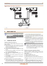
3.8
SYSTEM FILLING
How to fill up the system
After completing all water, electrical and gas connections:
1.
Pressurise (at least 20 psig) and vent the hydraulic circuit.
2.
Let water flow (with appliance off).
3.
Check and clean the filter on the inlet pipe.
4.
Repeat items 1, 2 and 3 until the pressure has stabilised
(at least 20 psig).
3.9
FUEL GAS SUPPLY
All gas piping must conform to the latest edition of
National
Fuel Gas Code ANSI Z223.1
and all local gas piping codes. In
Canada, the gas piping must conform to the
CGA Standard
CAN1 B149.1 e .2
, "
Installation Code for Gas Burning Appliances
& Equipment
" and local codes. Your gas utility must be contacted
regarding local requirements, type and size of gas lines. Safe
lighting and other performance criteria were met with the gas
manifold and control assembly provided on the appliance, when
it underwent the tests specified in the standards shown on the
rating plate.
Adequate combustion and ventilation air have to be provided,
in accordance with section 5.3 "Air for combustion and ventila-
tion" of the National Fuel Gas Code, ANSI Z223.1, appropriate
sections of the Natural Gas Installation Code, CAN/CGA B149.1,
or the Propane Installation Code, CAN/CGA B149.2, or applicable
provisions of the local building codes.
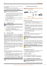
Gas connection
▶
1/2" F
on the right, at the bottom, connection plate (Figure 1.2
▶
Install an anti-vibration connection between the appliance
and the gas piping.
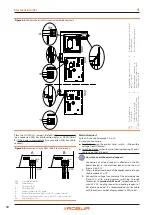
▶
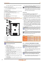
An approved union should be installed in the gas line near
the unit and downstream of any external shut-off valve that
may be required by local codes (Figure 3.4
p. 23).
▶
Be sure to use materials resistant to the LPG corrosive action
when making pipe connections. Use an approved sealing
compound resistant to propane gas on all male pipe threads.
The appliance and its gas connections must be leaked
tested before placing it in operation.
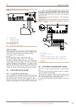
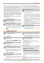
Figure 3.4
Typical gas connection
sediment trap
from gas
supply
approved gas
shut-off valve
approved union
to unit
Mandatory shut-off valve
▶
Provide a gas shut-off valve (manual) on the gas supply line,
next to the appliance, to isolate it when required.
▶
Perform connection in compliance with applicable regula-
tions.
▶
The appliance and its individual shut-off valve must be dis-
connected from the gas supply piping system during any
pressure testing of the gas piping system at test pressures
in
excess of 1/2 psig
.
▶
The appliance must be isolated from the gas supply piping
system by closing its individual shut-off valve during any
pressure testing of the gas piping system at test pressures
equal to or less than 1/2 psig
.
Gas pipes sizing
The gas pipes must not cause excessive pressure drops and, con-
sequently, insufficient gas pressure for the appliance.
Supply gas pressure
Inlet gas pressure to the appliance must not exceed 14.0
inch WC.
The appliance gas supply pressure, both static and dynamic,
must comply with the manufacturer's specifications (Table
5.1
p. 31), with tolerance ± 15%. Inlet gas pressure to the unit
must not exceed 14.0 inch WC on natural gas or propane gas.
The minimum inlet gas pressure at the unit is 5.0 inch WC on
natural gas and 11.0 inch WC on propane gas.
Non compliant gas pressure may damage the appliance
and be hazardous.
Vertical pipes and condensate
▶
Vertical gas pipes must be fitted with siphon and discharge
of the condensate that may form inside the pipe.
▶
If necessary, insulate the piping.
LPG pressure reducers
With LPG the following must be installed:
▶
A first stage pressure reducer, close to the liquid gas tank.
▶
A second stage pressure reducer, close to the appliance.
3.10
COMBUSTION PRODUCTS EXHAUST
Compliance with standards
The appliance is approved for the connection of the flue


