


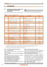


Electrical installer
Installation, use and maintenance manual – Calorio M
17
4
that it seats against the support bracket (see Figure
13. Secure the gas-fired convector to the support bracket
by means of the two side screws as shown in Figure
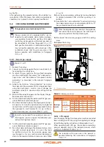
Figure 3.10
Attachment detail
A Bracket end for hooking to the gas-fired convector
B
Lateral eyelets for fixing to the bracket
A
B
3.5.2
Install the windproof terminal
1. When the appliance is installed, place the aluminium
windproof terminal to the outdoor wall so that it en-
gages with the end of the flue gas pipe and mark the
position of the three holes for the expansion plugs
(see Figure 3.11
p. 17). The terminal must be fitted
with the flue outlet grille arranged vertically.
2. Remove the terminal and drill the fixing holes (6 mm Ø
for the supplied wall plugs).
3. Reassemble the terminal and secure it with the screws
using the relevant plugs (see Figure 3.11
Figure 3.11
Windproof terminal fixing
4
ELECTRICAL INSTALLER
4.1
WARNINGS
General warnings
Read the warnings in Chapter III
p. 4, provid-
ing important information on regulations and on
safety.
Compliance with installation standards
Installation must comply with applicable regula-
tions in force, based on the installation Country
and site, in matters of safety, design, implementa-
tion and maintenance of electrical systems.
Installation must also comply with the manufactur-
er's provisions.
Live components
After placing the appliance in the final position,
and prior to making electrical connections, ensure
not to work on live components.
Earthing
The appliance must be connected to an effective
earthing system, installed in compliance with reg-
ulations in force.
It is forbidden to use gas pipes as earthing.
Cable segregation
Keep power cables physically separate from signal
ones.
Do not use the power supply switch to turn the
appliance on/off
Never use the power supply switch to turn the ap-
pliance on and off, since it may be damaged in the
long run (occasional blackouts are tolerated).
To turn the appliance on and off, exclusively use
the suitably provided control device.
4.2
ELECTRICAL POWER SUPPLY
Provide (by the installer) a protected single-phase line
(230 V 1-N 50 Hz).
How to connect the power supply
1. To connect the gas-fired convector to the mains power
supply, simply wire the supplied 3-pole plug as shown
in Figure 4.1
p. 18 using 3x0,75 mm² cable.
2. Insert the previously wired 3-pole plug into the socket
located on the lower right of the gas-fired convector
frame.


