


CANBus Networking Manual
9
Introduction to CAN Hardware signaling
Introduction to CAN Hardware signaling
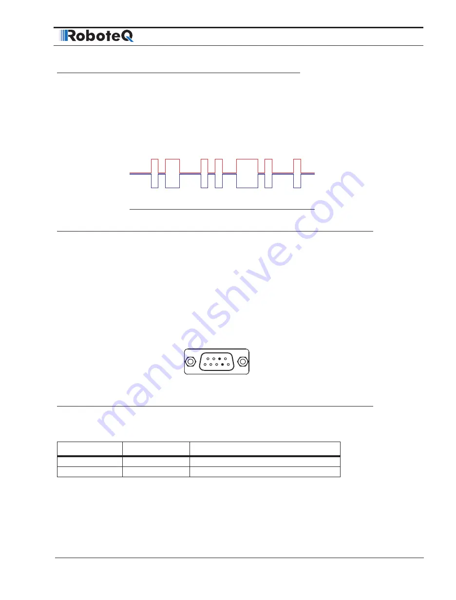
CANbus uses differential signals, which is where CAN derives its robust noise immunity
and fault tolerance. The two signal lines of the bus, CANH and CANL, are biased to around
2.5 V. A logical “1” (also known as the dominant state) on the bus takes CANH around 1
V higher to around 3.5 V, and takes CANL around 1 V lower to 1.5 V, creating a typical 2V
differential signal as shown in Figure 1-2.
0
2.5V
1.5V
3.5V
0V
0 0
0
0 0 0
0
0 0
0
0 0 0
0 0
1
1 1
1
1
1 1 1
1
1
Figure 1-2: CANbus signaling
Differential signaling reduces noise coupling and allows for high signaling rates over twist-
ed-pair cable. The High-Speed CANbus specifications (ISO 11898 Standard) are given for
a maximum signaling rate of 1 Mbps with a bus length of 40 m with a maximum of 30
nodes. It also recommends a maximum unterminated stub length of 0.3 m.
CAN Bus Pinout
Depending on the controller model, the CAN signals are located on the 9-pin, 15-pin or
25-pin DSub connector. Refer to datasheet for details.
1
1
5
6
9
13
14
25
FIGURE 1-3. DB9.Connector pin locations
The pins on the DB9 connector are mapped as described in the table below.
TABLE
1-
1. CAN Signals on DB9 connector
Pin Number
Signal
Description
2
CAN_L
CAN bus low
7
CAN_H
CAN bus high


