background image

7

GB

markings identifying the terminals in your plug, proceed as follows.

- The wire which is coloured green and yellow must be connected to the terminal in the plug which is

marked with the letter 

or by the earth symbol or coloured green or green and yellow.

- The wire which is coloured blue must be connected to the terminal which is marked with the letter 

or

coloured black.

- The wire which is coloured brown must be connected to the terminal which is marked with the letter 

or

coloured red.

ATTENTION: Do not forget to use adequate plugs to the support brackets. Enquire after the manu

-

facturers. Do an embedding if necessary. The manufacturer accepts no responsibility in case of a 
faulty hanging due to the drilling and the setting up of plugs.

GB

1) Unpack the hood parcel.

• LAYING OUT BEFORE FITTING THE HOOD

2) Mark the centre of the cooking appliance onto the ceiling with a plumb line. Draw the horizontal axes 

running parallel to the stove top onto the ceiling as illustrated 

Fig. 1

.

3) Place the drill gauge centred on the axes aligning the axes  on the drill gauge centrally over these 

axes as illustrated 

Fig. 2b

.

4) Remove the self-tapping screws, which fix the chimney 

item 7

 to the metal frame bracket as illustrated 

in 

Fig. 2a 

and then remove both sides of the upper chimney stacks.

5) Unplug the connectors 

and

 separate the motor housing from the canopy unscrewing the screws TH 5 

x 16 

Fig. 10&11

.

• 

FITTING THE CANOPY BRACKET

6) Mark the positions on the ceiling for :      - The cut-out for the ducting  Ø 150 mm in the extraction 

mode and Ø 200 mm in the remote mode when ducting runs through the ceiling.


                                                - The mains supply cords.


                                                - The 4 fixing holes for Ø 10 mm nuts and bolts.

Drill the different holes with the appropriate masonry bit. When fixing the cooker hood to a plasterboard 

ceiling ensure it is reinforced as illustrated in 

Fig. 3

 and attach using four Ø10mm nuts and bolts; ensuring 

the bolts as sleeved between the plasterboard and the joist supports to prevent the ceiling being damaged 

when the bolts are tightened up.

If the ceiling is concrete, use eight Ø 10 mm steel rawl bolts. Plastic rawl plugs must not be used.

7) Remove the deflector 

Fig. 4

.

8) The height of the cooker hood can be adjusted in 50 mm stages. 650 mm when fitting above an 

electric hotplate and 700 mm when fitting above a gas hotplate. Select the height required using the 

measurements illustrated in 

Fig. 5

 and fix the metal diffuser to the frame of the chimney brackets using 

the height 5 x 10T hexagonal headed screws. A drawing on the drill gauge defines the positioning for the 

controls.

9) Check the vertical of the chimney.

• DUCTING

The hood is more effective when used in the extraction mode (ducted to the outside). When the cooker 

hood is ducted to the outside, charcoal filters are not required.

The ducting used must be 150 mm (6 INS), rigid circular pipe and must be manufactured from fire retard-

ant material, produced to BS.476 or DIN 4102-B1. Wherever possible utilise rigid circular pipe which has 

a smooth interior, rather than the expanding concertina type ducting.

Maximum length of ducting run:  

-   4 metres with 1 x 90° bend.

-   3 metres with 2 x 90° bends. 

-   2 metres with 3 x 90° bends.

The above assumes our 150 mm (6 INS) ducting is being installed. Please note ducting components and 

ducting kits are optional accessories and have to be ordered, they are not automatically supplied with the 

chimney hood.

IN THE EXTRACTION MODE:

a.  Fit the non-return backflow flaps 

over the round outlet 

item 6

 on top of the canopy while pressing 

Содержание PROFIL 90 C EE INOX

Страница 1: ...TION ET D UTILISATION INSTRUCTIONS FOR INSTALLATION AND DIRECTIONS FOR USE MONTAGE UND GEBRAUCHSANWEISUNG LIBRETTO DI ISTRUZIONI INSTRUCCIONES DE INSTALACION E UTILIZACION MONTAGE EN GEBRUIKSHANDLEIDING PROFIL CENTRALE ...

Страница 2: ...NSTALACION DEL APARATO FUNCIONAMIENTO CONSEJOS DE UTILIZACION MANTENIMIENTO GARANTIA Y ASSISTENCIA TECNICA NOTA GB CONTENTS ELECTRICAL WIRING INSTALLATION ADVICE FITTING THE APPLIANCE OPERATION USEFUL HINTS MAINTENANCE GUARANTEE AND AFTER SALES SERVICES REMARKS I CONTENUTI COLLEGAMENTO ELETTRICO CONSIGLI DI INSTALLAZIONE POSA DELL APPARECCHIO FUNZIONAMENTO CONSICLI DI UTILIZZO MANUTENZIONE GARANZI...

Страница 3: ...accordée à un conduit de ventilation mécanique contrôlée V M C Lorsqu on évacue l air vicié dans un conduit d évacuation veiller à ce que celui ci ne soit pas déjà exploité à véhiculer des gaz ou fumées provenant d appareils alimentés par une énergie autre qu électri que Positionner le plan de cuisson au plus près de l évacuation et éviter la formation de coudes sur la gaine afin de réduire au max...

Страница 4: ...de colliers ou de ruban adhésif appropriés Fig 8 b Raccorder électriquement la hotte Voir paragraphe Raccordement Electrique c Monter la partie supérieure du conduit Rep 7 sur le support de hotte Puis le fixer par leurs vis Fig 2a d Vérifier de nouveau l aplomb du conduit e Enfiler la partie inférieure Rep 5 sur la partie supérieure du conduit La maintenir en position en dévissant légèrement 2 vis...

Страница 5: ...et vitesse en gardant la touche enfoncée jusqu à l obtention de la vitesse désirée Le niveau de vitesse est visualisé par les leds 2 3 4 qui s allument au fur et à mesure de l accroissement de la vitesse Led 2 niveau minimum Led 2 et 3 niveau intermédiaire Led 2 3 et 4 niveau élevé Un débit d aspiration maximal peut être obtenu directement en appuyant sur la touche vitesse intensive 5 F c Fonction...

Страница 6: ...ique qu il faut nettoyer les filtres métalliques voir paragraphe entretien Pour accéder à la remise à zéro de la fonction indiquant la saturation des filtres la lumière doit être éteinte et le moteur arrêté Appuyer sur la touche pendant 3 à 4 secondes Le clignotement des Leds 1 2 3 4 et 5 confirme la remise à zéro Indication de saturation des filtres charbon Après 400 heures de fonctionnement 2 br...

Страница 7: ...ICE APRÈS VENTE En cas d anomalie de fonctionnement prévenez votre installateur qui devra vérifier l appareil et son raccordement Dans le cas où un composant électrique viendrait à être endommagé celui ci ne peut être remplacé que par un atelier de réparation reconnu par le fabricant car des outils spéciaux sont nécessaires Débrancher complètement l appareil Exigez toujours l utilisation de pièces...

Страница 8: ...s are fitted ensure that there is an adequate supply of fresh air to the room Ensure the kitchen is fitted with an airbrick which should have a cross sectional measurement equivalent to the diameter of the ducting being fitted if not larger The ducting system for this cooker hood must not be connected to any existing ventilation system which is being used for any other purposes or to a mechanicall...

Страница 9: ... 10 mm nuts and bolts Drill the different holes with the appropriate masonry bit When fixing the cooker hood to a plasterboard ceiling ensure it is reinforced as illustrated in Fig 3 and attach using four Ø10mm nuts and bolts ensuring the bolts as sleeved between the plasterboard and the joist supports to prevent the ceiling being damaged when the bolts are tightened up If the ceiling is concrete ...

Страница 10: ... the chimney f Fix the charcoal filter retaining bracket item 4 onto the underside of the casing using the self tapping screws provided ensuring thebracket is fitted with the screws to the fore f Pull on the lower chimney item 5 and secure it temporarily unscrewing a little bit the lower self tapping screws as illustrated in Fig 9 FITTING THE CANOPY ONTO THE CHIMNEY 10 Place the canopy under the c...

Страница 11: ...D button 5 to switch OFF the boost setting immediately It is advisable too that you should leave it running in the boost setting for approximately 5 minutes after finishing Pre set stop of the boost speed A pre set stop after 5 minutes of the boost speed is available Your cooker hood is supplied with a deactivated pre set stop of the boost speed To use the cooker hood with a pre set stop of the bo...

Страница 12: ...ated remote control receiver To use the cooker hood with a remote control re programme the hood as follows Press the LED button Lighting 1 while the motor and lights are switched OFF until the LED lights 1 will flash to confirm the programme has been activated One flash of the LED lights 1 function is switched OFF Two flashes of the LED lights 1 function is switched ON Caution the remote control h...

Страница 13: ...ng the cooker hood Metal Grease Filters The metal grease filters absorb grease and dust during cooking to help keep the cooker hood clean inside The grease filters should be cleaned once a month or more frequently if the hood is used for more than 3 hours per day To remove and replace the metal grease filters Remove the metal grease filters one at a time by releasing the catches on the filters the...

Страница 14: ...s Guarantee does not cover Damage or calls resulting from transportation improper use or neglect the replacement of any light bulbs or filters or removable parts of glass or plastic These items are considered to be consumable under the terms of this guarantee 8 REMARKS This appliance complies with European regulations on low voltages Directive 2006 95 CE on electrical safety and with the following...

Страница 15: ...ksichtigen Die Dunstesse darf keinesfalls an eine Entlüftungsleitung mit Unterdruck angeschlos sen werden Die Abluft darf nicht in einen Schornstein geleitet werden der für die Abgase von Koch oder Heiz Geräten Kohle Öl oder Gas Öfen oder Herde benutzt wird Die Kochstelle und damit auch die Dunstesse so planen und installieren daß möglichst kurze Wege für eventuelle Abluft Rohrleitungen erreicht w...

Страница 16: ...l senkrecht im Lot stabil montiert ist ANSCHLUSS Im Abluftbetrieb a Die Rückstauklappe C am Gebläseausgang anbringen Pos 6 Dann den Schlauch am Geräteaus gang anschliessen Benutzen Sie zur Befestigung entweder passende Schlauchschellen oder Klebe band Fig 8 b Das Gerät ans Wechselstromnetz anschliessen siehe Abschnitt Netzanschluss c Den Oberteil des Kamins Pos 7 an das Trägergestell hängen Dann m...

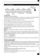
Страница 17: ...rd gereinigt und dann aus dem Haus geführt Motor und Beleuchtung müssen abgeschaltet sein Auf den Bedienknopf bis zum Blinken aller 5 LEDs drücken Zwei Blinken aller 5 LEDs zeigen an Funktion Abluftbetrieb EIN B Grundsätzliche Funktionen Beleuchtung Wird durch Druck auf die Schaltertaste 1 Licht eingeschaltet Die LED 1 zeigt den Zustand der Beleuchtung an Gebläse Wird durch Druck auf die Schaltert...

Страница 18: ...tik für Gebläse Nachlauf Diese Funktion ermöglicht nach Beendigung des eigentlichen Kochvorganges das zeitlich begrenzte Absaugen Nachlaufzeit der letzten Kochschwaden um danach automatisch Gebläse und Beleuchtung auszuschalten Um Zugang zur Programmierstufe dieser Funktion zu erhalten müssen Beleuchtung und Motor am Bedienungspult ausgeschaltet sein Die Esse muß aber am Stromnetz angeschlossen se...

Страница 19: ...inige Zeit nachlaufen zu lassen Für die Speisen die wenig Dampf entwickeln verwenden Sie vorzugsweise die kleine Geschwindigkeit WICHTIG NIEMALS UNTER DEM GERÄT FLAMBIEREN Niemals eine große Flamme bei eingeschalteter Dunstesse unbedeckt lassen Wenn der Topf weggenommen wird ist die Flamme abzuschalten oder für einen kurzen Zeitraum auf kleinste Stellung zu drehen trotzdem aber unbedingt im Auge z...

Страница 20: ...ich anerkannt Von der Garantieleistung ausgenommen sind Die Beleuchtung Klassik und Halogenbeleuchtung Die Filter Die Filter sind als Verbrauchsgut anzusehen 8 WICHTIGE HINWEISE Dieses Gerät entspricht den europäischen Niederspannungsrichtlinien 2006 95 EWG zur elektrischen Sicherheit den europäischen Richtlinien 2004108 EWG zur elektromagnetischen Verträglichkeit und den Richtlinien 93 68 EWG zur...

Страница 21: ...e collegata ad un condotto di ventilazione meccanica controllata V M C Qualora l aria viziata fosse scaricata in un condotto d evacuazione verificare che quest ultimo non sia già utilizzato per evacuare gas o fumi provenienti da apparecchi alimentati da un energia diversa da quella elettrica Posizionare il piano di cottura in corrispondenza della zona di evacuazione della cappa ed evitare la posa ...

Страница 22: ...elettricamente la cappa vedi paragrafo collegamento elettrico c Montare la parte superiore del camino Rif 7 sul supporto della cappa e fissarlo con le apposite viti Fig 2a d Verificare di nuovo l appiombo del camino e Infilare la parte inferiore Rif 5 sulla parte superiore del camino Mantenerla in posizione svitando leggermente 2 viti del camino superiore Fig 9 Versione Filtrante a Fissare il diff...

Страница 23: ...ossibile modificare la portata d aspirazione della cappa tenendo premuto il tasto velocità o velocità fino ad ottenere la velocità desiderata Il livello di velocità é visualizzabile tramite i Leds 2 3 4 i quali si accendono progressivamente con l aumentare della velocità Led 2 livello minimo Leds 2 e 3 livello intermedio Leds 2 3 e 4 livello alto La portata di aspirazione massima puo essere dirett...

Страница 24: ... di funzionamento della cappa 2 brevi lampeggi del Led 1 indicano che é necessario sostituire i filtri a carbone attivo e pulire di nuovo i filtri metallici Per attivare questa funzione luci e motore devono essere spenti Premere il tasto per 10 secondi 1 lampeggio dei Leds 1 2 3 4 e 5 funzione disattivata 2 lampeggi dei Leds 1 2 3 4 e 5 funzione attivata Il procedimento di sostituzione della cartu...

Страница 25: ...l caso in cui il cavo fosse danneggiato dovrà essere sostituito esclusivamente da un centro di riparazione consigliato dal fabbricante poiché la riparazione prevede l utilizzo di attrezzature apposite Staccare la spina dell apparecchio Esigete sempre l utilizzo di pezzi di ricambio originali in quanto il non rispetto di questa prescrizione potrebbe compromettere la sicurezza dell apparecchio e met...

Страница 26: ...r instalada a un conducto de ventilación mecánica controlada V M C En caso de que el aire viciado fuese conducido por un conducto de evacuación hay que verificar que dicho conducto no corresponda a tuberías de evacuación de humos causados por combustión Colocar el plano de cocción teniendo en cuenta la zona de evacuación de la campana y evitar la instalación de ángulos que podrían reducir la poten...

Страница 27: ...ricamente la campana Ver parafo Conexión Electrica c Colocar la parte superior de la chimenea Rep 7 en el soporte de la campana Fijar lo todo con ellos tornillos Fig 2a d Verificar de nuevo la balanza de la chimenea e Colocar la parte inferior Rep 5 de la chimenea en la parte superior de la chimenea Mantenerla en posición desatornillando un poco los 2 tornillos de la chimenea superior Fig 9 Versió...

Страница 28: ... la campana con la ayuda de los botones de velocidad y velocidad apretando sobre el botón elegido hasta que la velocidad alcanzada sea la deseada El nivel de velocidad se visualiza a través de los LEDS 2 3 4 que se encienden al mismo tiempo que van pasando las velocidades LED 2 NIVEL MÍNIMO LED 2 Y 3 NIVEL INTERMEDIO LED 2 3 Y 4 NIVEL MÁXIMO La aspiración máxima puede obtenerse también apretando d...

Страница 29: ...5 minutos 2 parpadeos parada pasados 10 minutos 3 parpadeos parada pasados 15 minutos INDICACIÓN DE SATURACIÓN DE LOS FILTROS METÁLICOS Al cabo de 200 horas de funcionamiento un breve parpadeo del LED 1 indicará que los filtros metálicos deben limpiarse ver párrafo de mantenimiento Para acceder a la puesta a cero de la función de aviso de saturación de filtros la luz deberá estar apa gada y el mot...

Страница 30: ... apertura para la evacuación del aire Conducto de evacuación Verificar cada 6 meses el buen flujo del aire viciado Observar las prescripciones reglamentarias locales sobre la evacuación del aire viciado Alumbrado Antes de cualquier intervención en la campana ponga el interruptor de encendido de luces en posición apagado No superar la potencia indicada y no cambiar el tipo de lámpara 7 GARANTIA Y A...

Страница 31: ...componentes de alta calidad que pueden ser reciclados y reutilizados Deberá informarse sobre el sistema de reciclaje local separado para productos eléctricos y electrónicos Siga las normas locales y no se deshaga de los productos usados tirándolos en la basura normal de su hogar El reciclaje correcto de su producto usado ayudará a evitar consecuencias negativas para el medio ambiente y la salud de...

Страница 32: ...en welke al gebruikt wordt voor de afvoer van lucht of gassen die afkomstig zijn van apparaten die op een andere vorm van energie lopen dan electriciteit Plaats de kookplaat zo recht mogelijk onder de afzuigkap en maak het aantal bochten in de afvoer zo gering mogelijk Op deze wijze wordt de meest effectieve afzuiging bereikt Zorg bij het installeren van een afzuigkap altijd dat de lucht in de rui...

Страница 33: ...duid op de boormal 9 Controleer de loodrechte stand van de schacht AANSLUITING Uitvoering met luchtafvoer a Plaats de terugslagklap C op de uitgang van het apparaat 6 en sluit de flexibele buis aan op de afvoer naar buiten en op de uitgang van het apparaat Bevestig het geheel met geschikte beugels of kleefband Afb 8 b Maak de elektrische aansluitingen van de afzuigkap Zie hoofdstuk Elektrische aan...

Страница 34: ... Druk op de toets de motor en de verlichting zijn uitgeschakeld OFF totdat de 5 ledjes twee keer knipperen om te bevestigen dat de wasemschouw gebruiksklaar is voor recirculatie Omzetten naar afzuiging de wasemschouw is geschikt voor luchtafvoer naar buiten Druk op de toets de motor en de verlichting zijn uitgeschakeld OFF totdat de 5 ledjes één keer knipperen om te bevestigen dat de wasemschouw g...

Страница 35: ...an 15 min 1 oplichtingen van leds 1 5 bevestigingen de annulatie van deze functie Indicatie verzadiging van de metaal filters Na ongeveer 200 uren gebruik zal er een Led 1 kort oplichten om aan te geven Dat de metaal filters dienen gereinigd te worden zie onderhoud Om deze functie terug te resetten laat U het licht branden en moet de motor afstaan Druk vervolgens op de toets gedurende 3 à 4 second...

Страница 36: ... Deze maatregel voorkomt het gevaar van brand Behuizing Gebruik geen natte doeken om de behuizing te reinigen Het gebruik van een milde zeep in combinatie met een vochtige doek wordt aangeraden Steek geen handen of andere objecten in de luchtinlaat Afvoerkanaal Controleer ieder half jaar of het afvoerkanaal niet verstopt is conform de lokale regels t a v luchtafvoerkanalen Verlichting Voordat even...

Страница 37: ...orm is de Europese Richtlijn 2002 96 EC Uw apparaat werd ontworpen met en vervaardigd uit onderdelen en materialen van superieure kwaliteit die gerecycleerd en opnieuw gebruikt kunnen worden Gelieve u te informeren in verband met het plaatselijke inzame lingsysteem voor elektrische en elektronische apparaten Gelieve u te houden aan de plaatselijke regle mentering en apparaten niet met het gewone h...

Страница 38: ... Connection Unit to BS 1363 Part 4 fitted with a 3 Amp fuse is a recommendedmains supply connectionaccessoryto ensure compliance with the Safety Requirements applicable to fixed wiring instructions The wires in this mains lead are coloured in accordancewith the followingcode Blue Neutral Brown Live As the colours of the wires in the mains lead of this appliancemay not correspondwiththe coloured ma...

Страница 39: ... 325 898 0 9 9 2 7 598 R 800 0 0 3 R 1 6 9 1 6 7 8 5 3 288 8 8 2 5 2 3 1 6 9 1 6 7 8 5 3 9 2 7 8 9 8 R 800 R 300 ...

Страница 40: ...GREEN YELLOW VERT JAUNE GRÜN GELB GREY GRIS GRAU LIGHT BLUE BLEU CLAIR HELL BLAU PINK ROSE ROSA PURPLE MAUVE MALVER FARBIG WHITE BLANC WEISS YELLOW JAUNE GELB 10 µF 400 V Green Yellow G N U R E U E T S E H C S I N O R T K E L E E D N A M M O C R E I T I O B L E N A P N O T T U B H S U P G N U N E I D E B N R E F E G U O R A R F N I R U E T P E C E R L O R T N O C E T O M E R L E B A K H C A L F I ...

Страница 41: ... 1 2a 3 5 2b 7 220 210 50 50 50 50 50 ...

Страница 42: ...40 6 6a 6b 6c A 6d 4 ...

Страница 43: ...41 C 6 5 7 8 9 ...

Страница 44: ...42 10 11 5 ...

Страница 45: ...33 7 2 LR03 AAA 1 5V 1 GU10 50 W 230 V Code 12EC006 ACCESSOIRES ACCESSORI ACCESSORIES ACCESORIA ZUBEHÖRE ACCESSOIRES ...

Страница 46: ...34 A B C D E F F ...

Страница 47: ...35 G H I J K L ...

Страница 48: ...36 Composants Components Bauelemente Componenti Componentes Onderdelen R 7 5 6 4 8 ...

Страница 49: ...erie Numero de serie Serienummer Modèle Model Modell Modello Modelo Model Plaque Signalétique de la hotte Rating plate of the cookerhood Typenschild im Inneren der Dunstesse Etichetta all interno della cappa Typeplaatje van de afzuigkap Etiqueta de la campana ...

Страница 50: ......

Страница 51: ......

Страница 52: ...5 Rue des Rosiers Sainte Cécile B P 56 50800 VILLEDIEU LES POËLES France Tél 02 33 91 26 50 Fax 02 33 51 54 79 e mail com france roblin fr For outside France Tel 33 0 2 33 91 26 57 Fax 33 0 2 33 51 54 79 e mail com export roblin fr ...

Отзывы: