B E F O R E Y O U S TA R T
This quick-start guide contains some basic
instructions for balancing the Robin Pro
05R V2 Stabilizer. Setting up a stabilizer like
the Robin Pro 05R V2 is not complicated,
but it takes some fine-tuning. Don’t feel
discouraged if it takes a few tries to balance
the stabilizer—a little patience goes a long
way.
Before you start, set up your camera in the
exact way that you are going to use it when
shooting with the stabilizer. For example,
if you are going to use your camera’s LCD
panel, make sure to extend the panel before
mounting your camera onto the stabilizer.
Any change to the camera’s balance will
change its center of gravity, and make it
necessary to readjust the stabilizer.
S E T U P
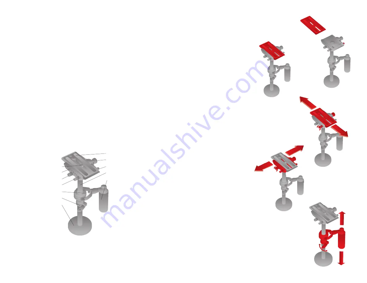
1. Remove the quick-release plate from the
stabilizer by holding down the quick-release
locking button. Slide the plate off the
mount.(Fig.1)
2. Mount your camera to the stabilizer’s
quick-release plate by lining up the 1/4
″
-20
threaded bolt and screwing it in clockwise.
Some devices, like a cell phone, may need an
additional mounting accessory for secure
attachment.
3. With your device on the plate, hold down
the quick-release locking button on the
stabilizer mount and slide the plate back in.
(Fig. 2)
4. Center your device as best as possible on
top of the stabilizer by using the forward/
backward and left/right adjustment knobs.
(Fig. 3-4)
B A L A N C I N G T H E S TA B I L I Z E R
1. Now it’s time to balance your stabilizer.
Grab the stabilizer’s handle and see how it
balances. It will likely not be perfectly level
at first. (Fig. 3-4)
2. Adjust the height of the gimbal on the
center column by loosening the gimbal
locking collar and slide to the desired
height. (Fig. 5)
3. Secure the gimbal by tightening the
locking collar. Repeat these steps until the
stabilizer remains vertically balanced while
you hold it by the handle.
Fig. 1
Fig. 2
Fig. 4
Fig. 5
1.
Sled
2.
Quick-release plate
3.
1/4
″
-20 mounting
threads
4.
Quick-release locking
knob
5.
Locking-pin release
button
6.
Forward/backward
adjustment knob
7.
Left/right adjustment
knob
8.
Handle
9.
Center column
10. Gimbal
11. Gimbal locking collar
12. Counterweight
O V E R V I E W
1
3
5
4
2
9
8
7
6
10
11
12
Fig. 3


