3
IMPORTANT SAFETY INFORMATION
WARNING:
• Always turn off power at main fuse or circuit breaker panel before
installing, removing, cleaning, or servicing thermostat.
• Read all the information in this manual before installing this
thermostat.
• This is a 24V AC low-voltage thermostat. Do not install on voltages
higher than 30V AC.
• All wiring must conform to local and national building and electrical
codes and ordinances.
• This is a dual powered thermostat that will operate on 24V AC
or batteries.
• Do not short (jumper) across terminals on the gas valve or at the
system control to test installation. This will damage the thermostat
and void the warranty.
• Do not connect ground to any terminal in this unit.
• This thermostat is configured with automatic compressor protection
to prevent damage because of short cycling or extended power
outages. Short cycle protection provides a delay between
compressor cycles on heat pumps.
Replacing Existing Thermostat
1. Turn off power to heating and cooling system.
2. Remove cover from old thermostat to expose wires.
3. Disconnect wires one at a time from existing terminals. Use
enclosed labels to mark existing wires. Refer to cross references in
Table 1 if existing wiring does not directly match the labels.
4. Remove existing thermostat base from wall.
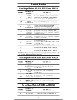
Table 1
Old Terminal
New Label
Description
R, RH/R, V-VR or VR-R
R/RH
24V AC Return
RC
RC
24V AC Cooling Transformer
C, X or B
C
24V AC Transformer Common Side
F or G
G
Fan Control Relay
Y, Y1 or M
Y1
1st Stage Cooling Circuit
W1 or W
W1
1st Stage Heating Circuit
Y2
Y2
2nd Stage Cooling Circuit
W2 or W-U
W2
2nd Stage Heating Control
W3
E
3rd Stage Heating Control
E
E
Emergency Heating Control

