SECTION 12: I
NTEGRATION WITH
B
UILDING
M
ANAGEMENT
S
YSTEM
(BMS)
93
• If RX LED is solid, then the terminations are incor-
rect.
• If the network has greater than 32 devices or
exceeds 2000’ (610 m) a Repeater should be
installed.
• If a controller begins or ends a network segment,
a terminating resistor may be needed.
12.3 BACnet PTP
PTP is used to connect 2 distinct BACnet networks
so that information can be shared between the
networks. PTP uses an EIA-232 connection between
2 BACnet half-routers. This connection allows for 2
different BACnet networks to speak to each other,
even at different baud rates.
To set up the Modulating Controller for BACnet
PTP
1. Turn off power to control board.
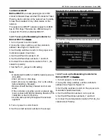
2. Using the rotary switches, set the controller's
address. Set the Tens (10's) switch to the tens digit
of the address and set the Ones (1's) switch to the
ones digit.
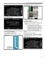
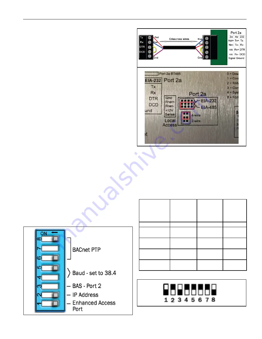
3. Set the Selector DIP Switches 4 and 5 for the
appropriate communications speed (9600, 19.2k,
38.4k, or 76.8k bps).
4. Set Comm Selector DIP Switch 3 to ON for Port 2.
Note:
Comm Selector DIP Switch 4 (Port 1) will be
set by the manufacturer.
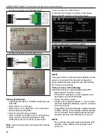
5. Set the DIP Switch Selector 6-8 for BACnet PTP.
The following example shows the DIP Switches set
for 38.4k, Port 2, and BACnet PTP.
6. Connect the communications wiring to Port 2a.
Wire Specifications
•
18–28 AWG; twisted pair preferable
• 50’ (15.24 m) maximum length
Note:
Do not power the device from the same
transformer that powers controller.
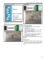
7. S
ee table below to wire control board to a modem.
8. Set the following DIP switch on the modem.
Note:
US Robotics External Modem is highly
recommended.
Modem (25-
pin)
Null Modem
Cable
Null
Modem
Cable
(9-pin)
S2-DB9
(9-pin)
Device
(5 pin)
TX - pin 2
TX - pin 3
TX - pin 3
TX - pin 1
RX - pin 3
RX - pin 2
RX - pin 2
RX - pin
2
DTR - pin 20
DTR - pin
4
DTR - pin
4
DTR - pin
3
DCD - pin 8
DCD - pin
1
DCD - pin
1
DCD -
pin 4
GND - pin 7
GND - pin
5
GND - pin
5
GND -
pin 5
Содержание CORAYVAC
Страница 2: ......
Страница 4: ......
Страница 69: ...SECTION 8 PROGRAMMING AND TROUBLESHOOTING THE SYSTEM 65 THIS PAGE LEFT INTENTIONALLY BLANK ...
Страница 71: ...SECTION 9 TROUBLESHOOTING 67 FIGURE 26 Vacuum pump does not turn on ...
Страница 73: ...SECTION 9 TROUBLESHOOTING 69 FIGURE 28 VFD showing a fault sign FIGURE 29 VFD input power issue ...
Страница 75: ...SECTION 9 TROUBLESHOOTING 71 FIGURE 31 Burner troubleshooting in manual mode ...
Страница 77: ...SECTION 9 TROUBLESHOOTING 73 After 45 second prepurge burners do not light continued ...
Страница 79: ...SECTION 9 TROUBLESHOOTING 75 FIGURE 34 APS does not close within 60 seconds after VFD receives run command ...
Страница 81: ...SECTION 9 TROUBLESHOOTING 77 FIGURE 36 Air Pressure Switch alarm ...
Страница 83: ...SECTION 9 TROUBLESHOOTING 79 FIGURE 38 Repeater troubleshooting ...
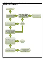
Страница 85: ...SECTION 9 TROUBLESHOOTING 81 BACnet MS TP troubleshooting continued ...
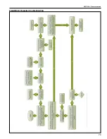
Страница 109: ...SECTION 13 TOUCHSCREEN TREE 105 Touchscreen Tree Overview continued ...
Страница 111: ...SECTION 13 TOUCHSCREEN TREE 107 FIGURE 47 Maintenance Unit FIGURE 48 Alarms ...
Страница 113: ...SECTION 13 TOUCHSCREEN TREE 109 FIGURE 51 Configuration Zones FIGURE 52 Configuration Unit ...
Страница 115: ...SECTION 13 TOUCHSCREEN TREE 111 FIGURE 55 Touchscreen System FIGURE 56 Touchscreen Setup ...
Страница 118: ...ROBERTS GORDON CORAYVAC MODULATING HEATING CONTROL CONTROLLER INSTALLATION MANUAL 114 ...
Страница 119: ...SECTION 14 THE ROBERTS GORDON CORAYVAC COMPLETE MODULATING HEATING CONTROL LIMITED WARRANTY 115 ...

