SECTION 11: R
EPLACEMENT
P
ARTS
85
11.1 CORAYVAC
®
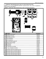
Modulating Heating Control Controller Replacement Parts
Caution:
Use only genuine ROBERTS GORDON
®
replacement parts. Use of parts not specified by
Roberts Gordon voids warranty.
FIGURE 41: CORAYVAC
®
Modulating Heating Control Controller Components
Description
Part Number
1
I/O Pro 812-U Control Board
10061001
2
Touchscreen (not shown)
10061002
3
Indoor Sensor (not shown)
10061003
4
Outdoor Sensor (not shown)
10081501
5
1 Pole Circuit Breaker
10061004
6
2 Pole Circuit Breaker
10061005
7
3 Pole Circuit Breaker
10061006
8
120v Control Power Circuit Breaker
10061007
9
30 Amp Disconnect Assembly
10061008
10
Transformer 24vac to 120vac
10061009
11
Amber LED Light
10061010
12
SPDT Relay 6A
10061011
13
4PDT Relay 15A
10061014
14
VFD Connection Terminal Block
10060170
15
24" x 24" x 7" Enclosure (not shown)
10061012
16
20" x 16" x 7" Enclosure (not shown)
10061013
17
1HP VFD Input: 115V, 1PH; Output: 230V, 3PH
10061201
1HP VFD Input: 230V, 1PH; Output: 230V, 3PH
10061202
2HP VFD Input: 230V, 1PH; Output: 230V, 3PH
10061203
1HP VFD Input: 460V, 3PH; Output: 460V, 3PH
10061204
2HP VFD Input: 460V, 3PH; Output: 460V, 3PH
10061205
1HP VFD Input: 230V, 3PH; Output: 230V, 3PH
10061206
2HP VFD Input: 230V, 3PH; Output: 230V, 3PH
10061207
88F0
E143900
TYPE: 002003
Power
Off On
Power
Gnd
24Vac
Port 1
485
ARC-
Shield
Net -
Net +
156
Port 2a
Rnet
Gnd
Rnet +
Rnet -
+12V
Xnet +
Xnet -
Gnd
Xnet Expansion
Local
Rnet+
Gnd
Sense
+12V
Rnet-
Access
EIA-485
EIA-232
Thermistor/
dry-contact/
Mode Select
Universal Input
mA
RTD
Volts
10V Max, 20mA Max
Inputs: All
UI-4
UI-3
UI-2
UI-1
Gnd
+
Gnd
Gnd
+
+
Gnd
+
8
7
6
5
4
3
2
1
UI-8
Gnd
UI-6
UI-7
UI-5
Gnd
+
+
Gnd
+
Gnd
+
UI-12
UI-11
UI-10
UI-9
+
Gnd
+
Gnd
Gnd
+
Gnd
+
24 Vdc
24 Vdc
200mA maximum
Auto Off On
0-20mA
0-10Vdc
Relay
Controller
Address
1's
10's
Archive Valid
Port 2a Rx
Port 2a Tx
Port 1 Rx
Port 1 Tx
Battery low
Ext. Batt.
Int. Batt.
External
Battery
Gnd
+3V
Status
Module
3V Lithium Battery
CR-123A
0 = Download required
3 = Comm setup error
1 = Control Program Error
4 = System error
8 = Formatting
2 = RAM full
Chase = OK
Status Codes
Class 2
ONLY Use Copper
24Vac, 50VA
Without Keypad:
26Vdc, 23W, 0.9A
Outputs
24Vdc Max, 50mA Max
Format
Pot
2-wire
4-wire
2 wire4 wire
Rx -
Net-
Net+
n/c
Tx -
Tx +
Rx +
n/c
EIA-232
DCD
Rx
Tx
DTR
Signal Ground
®
BACnet
Over ARCNET156 KBaud
Made in USA
Port 2a BT485
Port 1
Port 1 BT485
Conductors
2A, 50-60 Hz
Blinking Dot = 'Run'
On
Off
Enhanced
8
7
6
5
4
3
2
1
8
7
6
5
4
3
2
1
IP Addr
Assigned Default
10/100 BaseT
Ethernet Port E1
100
LAN LINK
®
8
7
6
5
See BAS Table Below
Protocols 6
MS/TP m
MS/TP s
Off
N2
On
Lon SLTA
Off
BAUD 4
5
9600 Off Off
19.2 K Off On
38.4 K On Off
76.8 K On On
On
Modbus
8
Off
Off
On
On
Off
4
BACnet
3
7
Off
On
Off
Off
Off
PTP
Off
Off
On
Access Port 2a
Lon OptionOff
On
On
2
1
UO-1
UO-2
UO-3
UO-4
UO-8
UO-7
UO-6
UO-5
On
Off
2
1
BAS Port
BAS Port Settings
Set Pot Full CW
24Vac
DO NOT APPLY 24Vac TO
UNIVERSAL OUTPUTS
External 24Vdc relay coil only
Brownout
3
UO-2
UO-1
2
1
UO-4
UO-3
6
5
4
7
8
6
UO-7
UO-6
UO-5
3
1
2
4
5
UO-8
7
8
+
Gnd
+
Gnd
+
Gnd
+
Gnd
+
Gnd
+
Gnd
+
Gnd
+
Gnd
Aux Power Out
Port 2b
Port 2a
IOPro812u
07/10/12
Rev 6
Open Energy
Management Equipment
26Vdc
I/O Pro 812u
CONTROLLER
3
10
U
OK
OK
TERMINAL BL
OCK 2
VFD2
OPTIONAL
4 5 6 7 8 9
2
1
11
3
10
4 5 6 7 8 9
2
1
11
V W
U V W
8
12
14
1
11
7
9
10
CB2
20A
11
14
12
COM
NO
NC
11
14
12
COM
NO
NC
(A1)
(A2)
TERMINAL BL
OCK 1
11
14
12
COM
NO
NC
(A1)
(A2)
11
14
12
COM
NO
NC
(A1)
(A2)
11
14
12
COM
NO
NC
(A1)
(A2)
11
14
12
COM
NO
NC
(A1)
(A2)
11
14
12
COM
NO
NC
11
14
12
COM
NO
NC
11
14
12
COM
NO
NC
11
14
12
COM
NO
NC
(A1)
(A2)
11
14
12
COM
NO
NC
11
14
12
COM
NO
NC
13
17
6
5
L1/L
POWER INPUT
POWER OUTPUT
POWER INPUT
POWER OUTPUT
CB1
VFD1
VFD2
Disconnect, 30A
L2
U1 V1 W1
U2 V2 W2
G
G
G
L1
L3
CB1
24Vac
N1/Gnd
P1
P2
Z1
Z2
Z3
Z4
TRANSFORMER
24V
ac
24V
ac
N1
L2/N L3
L1/L L2/N L3
N G
G
N
L L L L
N N N N
G
24V
ac
24V
ac
N1 N1
SP
ARE
SP
ARE
24V
ac
RELA
Y 3
RELA
Y 2
RELA
Y 1
RELA
Y 5
RELA
Y 6
RELA
Y 4
Indicator Lights
Содержание CORAYVAC
Страница 2: ......
Страница 4: ......
Страница 69: ...SECTION 8 PROGRAMMING AND TROUBLESHOOTING THE SYSTEM 65 THIS PAGE LEFT INTENTIONALLY BLANK ...
Страница 71: ...SECTION 9 TROUBLESHOOTING 67 FIGURE 26 Vacuum pump does not turn on ...
Страница 73: ...SECTION 9 TROUBLESHOOTING 69 FIGURE 28 VFD showing a fault sign FIGURE 29 VFD input power issue ...
Страница 75: ...SECTION 9 TROUBLESHOOTING 71 FIGURE 31 Burner troubleshooting in manual mode ...
Страница 77: ...SECTION 9 TROUBLESHOOTING 73 After 45 second prepurge burners do not light continued ...
Страница 79: ...SECTION 9 TROUBLESHOOTING 75 FIGURE 34 APS does not close within 60 seconds after VFD receives run command ...
Страница 81: ...SECTION 9 TROUBLESHOOTING 77 FIGURE 36 Air Pressure Switch alarm ...
Страница 83: ...SECTION 9 TROUBLESHOOTING 79 FIGURE 38 Repeater troubleshooting ...
Страница 85: ...SECTION 9 TROUBLESHOOTING 81 BACnet MS TP troubleshooting continued ...
Страница 109: ...SECTION 13 TOUCHSCREEN TREE 105 Touchscreen Tree Overview continued ...
Страница 111: ...SECTION 13 TOUCHSCREEN TREE 107 FIGURE 47 Maintenance Unit FIGURE 48 Alarms ...
Страница 113: ...SECTION 13 TOUCHSCREEN TREE 109 FIGURE 51 Configuration Zones FIGURE 52 Configuration Unit ...
Страница 115: ...SECTION 13 TOUCHSCREEN TREE 111 FIGURE 55 Touchscreen System FIGURE 56 Touchscreen Setup ...
Страница 118: ...ROBERTS GORDON CORAYVAC MODULATING HEATING CONTROL CONTROLLER INSTALLATION MANUAL 114 ...
Страница 119: ...SECTION 14 THE ROBERTS GORDON CORAYVAC COMPLETE MODULATING HEATING CONTROL LIMITED WARRANTY 115 ...


