


SECTION 11: O
PERATION
AND
M
AINTENANCE
31 of 57
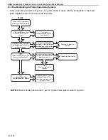
11.2.3 Start-Up the Gas Valve (All Gases)
11.2.3.1 Check Burner Gas Pressure
1. Remove the pl
u
g in the o
u
tlet (b
u
rner) press
u
re
test point and connect a press
u
re tap and a
manometer.
2. With the b
u
rner firing, meas
u
re the press
u
re on
the manometer. To adj
u
st the b
u
rner press
u
re,
remove the reg
u
lator cover from the valve and
t
u
rn the reg
u
lator adj
u
stment scre
w
to set the
req
u
ired b
u
rner press
u
re as stated in the
Technical Data Table for the correct gas and
model
on Page 53, Section 16.3 and Page 55,
Section 16.6
.
NOTE:
For t
w
o stage valve (High/Lo
w
operation)
check b
u
rner press
u
re in both operation modes. To
adj
u
st the b
u
rner press
u
re, remove plastic cover
from reg
u
lators and adj
u
st High and/or Lo
w
reg
u
lators as needed.
NOTE:
If the correct b
u
rner press
u
re cannot be
reached, then check the inlet press
u
re to the valve
w
ith the b
u
rner firing. See Technical Data Table
on
Page 53, Section 16.3 and Page 55, Section 16.6
for inlet press
u
re req
u
irement.
Do not continue to adjust the re
g
ulator if the
pressure is not chan
g
in
g
.
If the inlet press
u
re is too lo
w
to allo
w
correct b
u
rner
press
u
re setting, then the gas inlet press
u
re m
u
st be
corrected before completing the start-
u
p.
11.2.3.2 Check Gas Rate
1. After b
u
rner press
u
re adj
u
stment, allo
w
the
heater to operate for at least 15 min
u
tes and
then re-check settings. Adj
u
st press
u
re setting
if necessary.
2. Check gas flo
w
rate at gas meter. For t
w
o stage
valve, (High/Lo
w
operation) check gas flo
w
in
both operating modes.
3. T
u
rn off heater and electrical s
u
pply.
4. Remove the manometer and refit all covers to
the valve and tighten the scre
w
of the o
u
tlet
press
u
re tap.
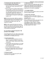
11.3 Pressure Switch
The press
u
re s
w
itch is factory pre-set for each
model and is not adj
u
stable.
11.4 External Controls
External controls may incl
u
de time s
w
itch, interlock
s
w
itch, room thermostat and frost thermostat.
Operate each control to ens
u
re that they f
u
nction
correctly. Set the s
w
itches (if eq
u
ipped) and
thermostat(s) to the
u
sers’ req
u
irements.
11.5 Complete Start-Up
Ens
u
re that all covers are fitted correctly and all test
points are properly sealed.
11.6 Instruction to the User
Explain the controls of the heater to the
u
ser
incl
u
ding ho
w
to t
u
rn it on and off,
u
sing the controls
eq
u
ipped on site.
Give this man
u
al to the
u
ser.
Ens
u
re that the
u
ser is sho
w
n and
u
nderstands the
importance of maintaining clearances to
comb
u
stibles
on Page 7, Figure 4
, installer
responsibility
on Page 5, Section 2
and
u
ser
instr
u
ctions
on Page 32, Section 12
and all
w
arnings defined in this man
u
al.
Содержание Combat UHD-Series
Страница 2: ......
Страница 4: ......
Страница 8: ......
Страница 28: ...UHD STANDARD DUCT FURNACE INSTALLATION OPERATION AND SERVICE MANUAL 20 of 57 Figure 13 Gas Connection ...
Страница 46: ...UHD STANDARD DUCT FURNACE INSTALLATION OPERATION AND SERVICE MANUAL 38 of 57 14 1 General ...
Страница 64: ...UHD STANDARD DUCT FURNACE INSTALLATION OPERATION AND SERVICE MANUAL 56 of 57 ...
Страница 66: ......
Страница 67: ......
Страница 68: ......
Страница 69: ......
Страница 70: ......


