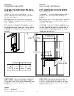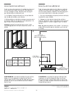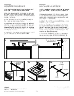
background image

23

No. de pièce / Pieza n.

°

 CB-209-1332 05/05/20

Vitality Cabinet / Vitality Gabinete

© 2020 Robern, Inc. 701 N. Wilson Ave. Bristol, PA  19007  U.S.A.

800.877.2376      

www.robern.com


Instructions d'installation  / Instrucciones de instalación 

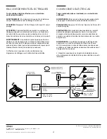
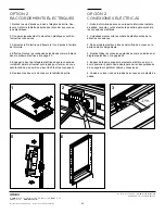
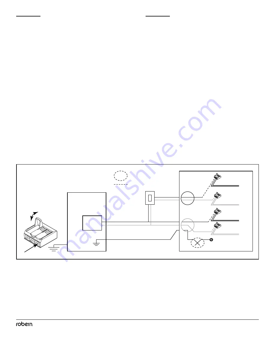
DISJONCTEUR

CORTACICUITOS

BLANC

BLANCO

MISE À  LA TERRE

BAJADA A TIERRA

NOIR

NEGRO

BLANC

BLANCO

MISE À  LA TERRE

BAJADA A TIERRA

NOIR

NEGRO

CONNEXION DE CHAMP

CONNEXIÓN DE CAMPO

120VAC

20A GFI

VARIATEUR

REGULADOR DE INTENSIDAD

LIGNE/NOIR

LINEA/NEGRO

NEUTRE/BLANC

NEUTRAL/BLANCO

NEUTRE/BLANC

NEUTRAL/BLANCO

LIGNE/ROUGE

LINEA/ROJO

3

RACCORDEMENTS ÉLECTRIQUES 

CONEXIONES ELÉCTRICAS

Tout le câblage doit être effectué par un électricien 

professionnel qualifié.

AVERTISSEMENT:

 Pour réduire le risque de choc électrique, 

coupez l’alimentation avant le câblage de l’armoire.

ATTENTION:

 Nécessite 120 VAC Classe A 20 Amp GFI circuit 

protégé.

ATTENTION: 

Ce produit doit être raccordé à un système de 

câblage permanent en métal mis à la terre ou un conducteur 

de terre doit être exécuté avec les conducteurs du circuit et 

branché à la borne de mise à la terre ou la borne sur le produit.

AVERTISSEMENT: 

Une armoire à option électrique doit être 

câblée à un circuit protégé par un Classe A GFCI (Disjoncteur 

de fuite à la terre) de 20 ampères si elle est utilisée dans des 

salles de bain et dans tous autres emplacements requis par le 

National Electric Code (Code électrique national).

3. Effectuer les connexions in-situ conformément au 

diagramme de câblage pour l’option électrique installée.

Todo el cableado debe ser realizado por un electricista 

calificado.

ADVERTENCIA:

 Para reducir el riesgo de descargas eléctri

-

cas, apague la alimentación antes de cablear el armario.

PRECAUCIÓN:

 Requiere 120 VAC de Clase A de 20 Amp GFI 

circuito prote gido.

PRECAUCIÓN: 

Este producto debe conectarse a un metal 

sistema de cableado permanente a tierra o un conductor 

de puesta a tierra se debe ejecutar con los conductores de 

circuito y conectado al terminal de tierra del equipo o al cable 

del producto.

ADVERTENCIA:

 Un gabinete de opciones eléctricas debe 

conectarse a un circuito protegido de Clase A de 20 amp 

GFCI (Interruptor de circuito de falla a tierra) cuando se usa 

en baños y en todas las demás ubicaciones requeridas por el 

Código eléctrico nacional.

3. Haga las conexiones en el lugar de la instalación de acu

-

erdo al diagrama de cableado de la opción eléctrica que esté 

instalando.

Содержание YC2430D4P1L3

Страница 1: ...ruction sheet contains information on how to install the Vitality series cabinets This series comes in various sizes Refer to specific model numbers for dimensions Read the specific instruction for ho...

Страница 2: ...number This chart references the model number for a 24 W x 30 H x 4 D Vitality cabinet Consult the Robern Price Book for a complete list of model numbers The model number is located inside of your cab...

Страница 3: ...ecommended by the manufacturer Never drop or insert any object into any opening Do not use outdoors WARNING Risk of electric shock Connect this furnishing to a properly grounded cir cuit only See Grou...

Страница 4: ...ion not all parts will be used 1 Single Door Vitality Cabinet 3 Glass Shelves 30 MSMK30D4P 40 MSMK40D4P Optional for surface mounting 2 Z Mounting Bars 2 Glass Side Panel SS712 3 Top Clip SS676 12 10...

Страница 5: ...s Hole Rough Opening RO for recessed installation in chart below D1 minimum 4 required or 2X4 construction Determine overall cabinet dimensions If recessing cabinet determine rough in dimensions See c...

Страница 6: ...LACK LINE RED NEUTRAL WHITE NEUTRAL WHITE 3 All wiring should be done by a qualified licensed electrician WARNING To reduce the risk of electrical shock shut off power before wiring the cabinet CAUTIO...

Страница 7: ...available Select the best option to make your installation easier Option 1 Connecting the FIELD POWER wires at the rear of the cabinet Option 2 Connecting the FIELD POWER wires inside the cabinet Remo...

Страница 8: ...emove rear plates to access internal wiring NOTE Wiring access opening closest to hinge side of cabinet contains dimmer switch connections 2 Carefully cut plastic tie before making the connections 3 F...

Страница 9: ...E Wiring access opening closest to hinge side of cabinet contains dimmer switch connections 2 Carefully cut plastic ties before making the connections 3 Feed the field wiring through the access holes...

Страница 10: ...nce above the top of the faucet including drain stop and at least 1 below the ceiling 2 Electrical field wiring Electrical feed through location is indicated below See page 5 for wire access locations...

Страница 11: ...et in rough in and make sure cabinet is plumb and level 4 Install a 10 X 2 screw SS674 through top mounting hole in cabinet side and screw into wall stud as shown Do not over tighten screw 5 Once cabi...

Страница 12: ...ll or tile 2 Electrical field wiring Electrical feed through location is indicated below See page 5 for wire access locations NOTE Make sure cabinet door has at least 1 25mm clearance above the top of...

Страница 13: ...ered 5a Use 10 X 2 screws SS674 provided to attach the Z Mounting Bar mounting strip to the wall 5b If no furring strip or stud is available use the provided wall anchors 203 1349 making sure that eac...

Страница 14: ...ting bar 8 Using the provided 10 X 2 screws SS674 attach the top of the cabinet to the wall through the top clips as shown NOTE If no stud is available use wall anchors as described in step 5b 9 Elect...

Страница 15: ...2A With the hinge slightly closed you can access the middle screw This screw will move your door front up and down adjusting the height 2B With the hinge fully extended you can access the front and b...

Страница 16: ...Place the Screw Caps SS672 over any exposed screw heads NOTE Do not store items in the cabinet area directly behind the hinge as damage may occur to cabinet or items 12 SS131 SS131 CAUTION Maximum she...

Страница 17: ...than those authorized by ROBERN At the expiration of the one year warranty period ROBERN shall be under no further obligation under any warranty expressed or implied including the implied warranty of...

Страница 18: ...structions pour l utilisation et la r f rence future Un inappropri es annule la garantie de l installation Cabinets install s ne peuvent tre retourn s Si vous rencontrez des probl mes avec votre cabin...

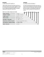
Страница 19: ...rieur de votre armoire Use la tabla a continuaci n para aprender c mo construir un n mero de modelo de gabinete de vitalidad Este cuadro hace referencia al n mero de modelo para un gabinete de vitalid...

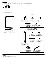
Страница 20: ...erficie 2 barre de montage en Z barra de montaje en Z 2 Panneau lat ral de verre Panel lateral de vidrio SS712 3 Support Sup rieur Montaje Superior SS676 12 10 x 1 2 h lice 10 x 1 2 tornillo SS672 12...

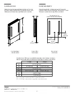
Страница 21: ...sions sp cifiques selon le mod le Determinar gabinete y las dimensiones de Si empotrar gabinete determinar las dimensiones toscamente en Vea la tabla para las dimensiones espec ficas del modelo A B D...

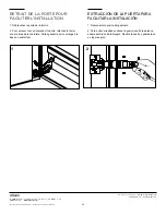
Страница 22: ...UR FACILITER L INSTALLATION EXTRACCI N DE LA PUERTA PARA FACILITAR LA INSTALACI N 1 D branchez la porte de l armoire 2 Pour enlever tout en soutenant la porte rel chez le levier sous le bras de la cha...

Страница 23: ...VERTISSEMENT Une armoire option lectrique doit tre c bl e un circuit prot g par un Classe A GFCI Disjoncteur de fuite la terre de 20 amp res si elle est utilis e dans des salles de bain et dans tous a...

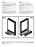
Страница 24: ...ire les c bles secteur alimentation peuvent tre raccord s l int rieur de l armoire Le retrait du couvercle lectrique int rieur de l tag re est requis L armoire peut tre enti rement c bl e apr s montag...

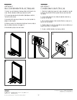
Страница 25: ...imentez le fil lectrique travers le trou d acc s dans la plaque comme illustr 4 Effectuez toutes les connexions lectriques comme indiqu dans le sch ma lectrique la page 23 5 R installez la plaque d ac...

Страница 26: ...lectrique dans le chemin de roulement arri re et tourner vers le bas pour fermer en vous assurant de ne pas sertir ou pincer les fils et les connexions 6 Replacez les deux vis d acc s sur la tablette...

Страница 27: ...os Encuentre las dimensiones de un determinado modelo de hacer abertura p gina 21 Nota Aseg rese de que la puerta del gabinete es de al menos 1 25 mm de espacio libre en la parte superior de la llave...

Страница 28: ...bages tel qu illustr Ne pas serrer trop les vis 5 Une fois que l armoire est d aplombs et niveau installez les vis 10 X 2 51 mm restantes dans les colombages Voir la page 32 pour l assemblage final 3...

Страница 29: ...Consulte la p gina 22 para ver las instrucciones de extracci n de la puerta 1 It es muy recomendable que la pared se enmarca detr s de los paneles de yeso o baldosa 2 Cableado de campo el ctrico alime...

Страница 30: ...cheville soit au ras du mur 5c Utilisez la vis n 10 SS674 et serrez la vis jusqu ce qu il y ait une forte r sistance NE PAS TROP SERRER 3 Centro de barra Z en la posici n del gabinete Aseg rese de Z...

Страница 31: ...partir de la bo te de meuble int rieur en Kit Side Testez l acc s de l armoire avant de ter miner l installation Boucher les vis avec les bouchons fournis Aller aux page 32 pour l assemblage final 6 D...

Страница 32: ...bisagras de la puerta tienen una funci n de ajuste de tres v as Estos ajustes se pueden hacer con un destornillador Phillips 2 2A Con la bisagra ligeramente cerrada puede acceder al tornillo central...

Страница 33: ...surfaces Lors du nettoyage vaporiser le tissu pas les surfaces armoire miroir ou surround Ne utilisez pas de produits nettoyants abrasifs sur aucune partie de l appareil d clairage 3 Inserte clara co...

Страница 34: ...rchandise doit tre retourn e frais de poste pr pay s par l acheteur Les r clamations sous cette garantie doivent tre transmises directement votre marchand 2020 ROBERN INC TOUS DROITS R SERV S Garant a...

Отзывы: