


3
EN
EN
2
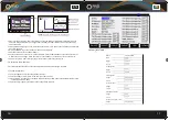
Product Introduction
Specifications and Series
Main Features
• Four independent output channels
• LIST programmable output sequence, 100 consecutive different settings
• LIST mode and normal mode can be switched automatically with one button
• Oscilloscope function for simultaneous display of voltage and current on four channels
• Oscilloscope screen capture via USB access to U disk
• U disk import and export output table data, and you can edit it by computer EXCEL
• Low chopping and low noise
• High resolution and precision with 5-digit display
• Remote measurement function
• External trigger control and switch control
• Supporting OVP, OCP and temperature protection
• Built-in USB/RS232/GPIB/LAN communication interfaces
Model
Output Voltage
Output Current
Output Power
RND 790- 00001
0-30V*4
0-5A*4
600W
?
0-30V*4
0-5A*4
720W
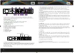
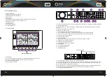
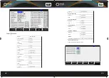
1. CH1 channel indication, refers to the constant output mode of the channel. When entering the output
mode of dynamic LIST, it becomes LIST-1
2. Output voltage indication, refers to the actual output voltage value of CH1
3. Output current indication, refers to the actual output current value of CH1
4. Output power indication, refers to the actual output power value of CH1
5. OVP and OCP setting and switch status, when OCP and OVP are OFF, it shows OFF while it indicates
the set value when OVP and OCP are ON.
6. CH1 set value of voltage and current
7. Output ON/OFF indication, and constant voltage and constant current mode indication of
channel output
8. CH1 constant output and button indication of dynamic LIST output
9. CH2 constant output and button indication of dynamic LIST output
10. CH3 constant output and button indication of dynamic LIST output
11. CH4 constant output and button indication of dynamic LIST output
12. USB flash disk insertion indication. When the USB flash disk is inserted, the logo will appear as a
USB font.
13. System configuration and button indication of function configuration
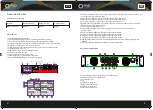
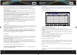
Rear Panel Introduction
1.
4 channel voltage output terminal, GND is the earth terminal
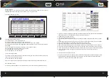
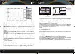
2 -3 External control port, as shown below:
4. AC power input port
5. Vent
6. USB communication port
7. RS232 communication port
8. LAN communication port
9. GPIB communication port
OFF CV
OFF CV
OFF CV
CH1
00.000V
0.0000A
00.000W
CH3
00.000V
0.0000A
00.000W
CH2
00.000V
0.0000A
00.000W
CH4
00.000V
0.0000A
00.000W
Vset:
Iset:
OVP:
OCP:
22. 900V
4. 1000A
OFF
OFF
Vset:
Iset:
OVP:
OCP:
22. 100V
4. 3000A
OFF
OFF
Vset:
Iset:
OVP:
OCP:
22. 000V
4. 2000A
OFF
OFF
OFF CV
Vset:
Iset:
OVP:
OCP:
22. 800V
4. 0000A
OFF
OFF
CH2/LIST
CH1/LIST
CH3/LIST
CH4/LIST
USBC
onfigure
Содержание 790-00001
Страница 1: ...www rnd electronics com RND Power Supply User Manual RND 790 00001...
Страница 13: ...www rnd electronics com...


