background image

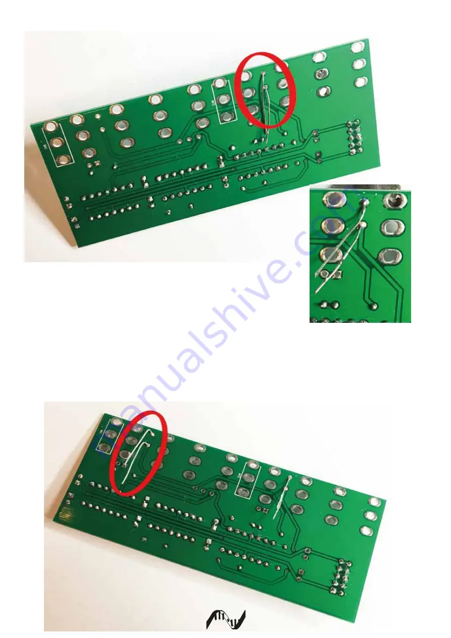
STEP 6 Place two of the cut off resistor legs into the holes just enough to see

           then poke through the other side and solder in place.

           This is for the Inverted Out socket which we will connect later.

STEP 7 Do the same with second Inverted Out socket.

r a

Содержание replicator v4

Страница 1: ...socket mouser 517 4814 3000 CP 3x TL074 mouser 595 TL074CN 2x 22uF Electro mouser 647 UMT1V220MDD 10pin IDC power mouser 571 5103308 1 10x Switchcraft Sockets mouser 502 35RAPC2AV 1x SPDT switch ON ON...

Страница 2: ...STEP 3 Install 3x 14 pin DIP sockets Notice orientation STEP 4 Install 6x 100n capacitors STEP 5 Install IDC power connector Notice orientation of center location slot r a...

Страница 3: ...t off resistor legs into the holes just enough to see then poke through the other side and solder in place This is for the Inverted Out socket which we will connect later STEP 7 Do the same with secon...

Страница 4: ...nector holes STEP 9 Install main filter caps 2x 22uf Observe polarity The positive is marked on the board STEP 10 Turn the board over to install the two Input Sockets The Box on the silkscreen indicat...

Страница 5: ...can be added to secure the Output sockets Once all the nuts are fastened solder the eight ouput sockets in place STEP 12 Install the Invert out sockets and secure in place The legs should line up wit...

Страница 6: ...nut the switch Then solder the three wires to the switch STEP 14 Install the two LEDS For Green to show Volts and Red to show Volts install with the LED s longer leg towards the power connector STEP...

Страница 7: ...STEP 17 Check that the 12V red stripe indicator appears at the backside of the PCB STEP 16 Insert the three TL074 s observing correct orientation r a...

Отзывы: