RNA PARU-Mini-S Скачать руководство пользователя страница 10


|

 10 


PARU Mini is a two-mass system. With PARU Mini, exciter mass and useful mass are connected to each 
other  by  spring  leaves  inclined  at  a fixed  angle.  The  usable  mass  also  includes  the  tooling.  The  vibratory 
system  is  excited  by  magnets.  This  results  in  an  oscillating  motion  of  the  usable  mass.  This  motion 
accelerates the parts in horizontal and vertical direction, causing them to move along the tooling. PARU Mini 
oscillates in the range of 100Hz (EU) resp. 120Hz (USA). The vertical amplitude is up to 30µm, the horizontal 
amplitude is up to 150 µm.   
 

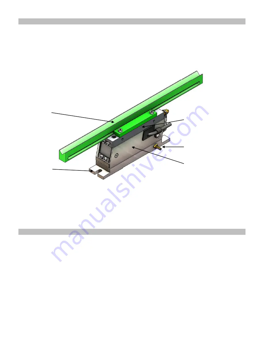
Fig. 4 illustrates a PARU Mini XS unit with a typical tooling (4) shown green. 


Fig. 4: PARU Mini XS with tooling (shown green) 

 
The parts handled are finally oriented and buffered by means of the tooling (4) and the part-specific sorting 
elements. Two M6 or M8 screws are used to fasten the PARU Mini to its mount via the stationary baseplate 
(1). The exciter mass (2) and useful mass (3 and 4) are the vibrating components. The tooling is part of the 
useful mass and is fastened to the useful mass plate (3) by means of clamps, for example. The connection 
for user’s earth (5) is located on the baseplate. 


We recommend you to observe following general conditions when designing tooling units for PARU Mini. 
The tooling must be a rigid body in order to transmit the motion of the useful mass in the best possible way. 
We  recommend  a  feed  rail  height-to-width  ratio  of  2:1  or  higher.  We  recommend  the  use  of  threaded 
assemblies suitable for rigid bodies.  
To ensure stability of the PARU Mini with minimum transmission of bearing forces to its mount, the rail should 
not exceed the maximum weight stated in chapter 2.2.  
The tooling centre of gravity should be located in the middle of the PARU Mini, and the centrifugal moment 
about the feeding axis of PARU Mini should be close to 0.  
 
For  virtual  validation  of  the  feeding  behaviour  and  system  tuning/matching  we  recommend  to    design  the 
tooling using the CAD dummy for PARU Mini and the simulation tool of Rhein-Nadel Automation GmbH.  


2.4. 

Functional description  

2.5. 

Tooling development  

4


3


Содержание PARU-Mini-S

Страница 1: ...Installation and Operating Instructions PARU Mini S PARU Mini XS...

Страница 2: ...tion 10 2 5 Tooling development 10 3 Installation Instructions 11 3 1 Shipping and handling 11 3 2 Installation 11 3 3 Commissioning 12 4 Operating Instructions 13 4 1 Operation 13 4 2 Tooling change...

Страница 3: ...35 EU Low Voltage 2014 30 EU Electromagnetic Compatibility EN 614 1 2006 A1 2009 EN ISO 13857 2008 EN 618 2002 A1 2010 EN ISO 14120 2015 EN ISO 12100 2010 EN 60204 1 2006 The relevant technical docume...

Страница 4: ...damage and minor or moderate injury Notice Indicates general information useful tips and recommendations which have no influence on the health and safety of PARU users The intended use of PARU Mini is...

Страница 5: ...prerequisite for working on the PARU Reading of the technical documents related to the PARU drive is part of this instruction session 2 Qualified personnel Qualified personnel are able to independentl...

Страница 6: ...fully exploit its functionality it is imperative that you use this product in conformity with this operating and installation instruction manual Beside the configuration of the tooling the controller...

Страница 7: ...80 Mass excl tooling kg 1 8 3 0 Power input VA 15 19 Current input A at 230V 0 07 0 08 Current input A at 110V 0 16 0 17 Magnet article code for 230V 39930322 39930334 Magnet article code for 110V 399...

Страница 8: ...U Mini all screws have property class 10 9 or better ISO 4762 M4 screws of leaf spring Nm 4 5 ISO 4762 M5 screws of leaf spring Nm 6 5 ISO 4762 M6 screws of leaf spring Nm 9 ISO 4762 M4 screws of spri...

Страница 9: ...ere frequency controllers with selectable output frequency are used an EMC metal gland and a shielded cable are provided The vibratory feeder is controlled by a low loss electronic control unit The ch...

Страница 10: ...vibrating components The tooling is part of the useful mass and is fastened to the useful mass plate 3 by means of clamps for example The connection for user s earth 5 is located on the baseplate We r...

Страница 11: ...npack and install it at the intended site After removing PARU Mini from its packing you should first make a visual inspection of all visible surfaces and clean the unit as necessary to remove any soil...

Страница 12: ...operating instructions for the control unit used As PARU Mini is incomplete machinery the interaction between PARU Mini and user s receiving station is to undergo a risk analysis to be conducted by u...

Страница 13: ...s Operation of PARU Mini is permitted only if the enclosure is installed and user s safety circuitry is functional Operators assigned by the equipment user can be trained on the PARU Mini by Rhein Nad...

Страница 14: ...l equipment Make functional test P h Tighten loose connections remove charred cables components Couplings connections P N h Observe tightening torques SRA Z drive Clean from dirt R w Pay attention to...

Страница 15: ...led according to their materials Please contact Rhein Nadel Automation GmbH if you want to return the PARU Mini unit Spare parts must satisfy the technical requirements specified by us This is always...

Страница 16: ...the individual batches from the setpoint parts Send the results to Rhein Nadel Automation GmbH and request a quotation for a tooling that is optimized for these varying part batches with the help of s...

Страница 17: ...ndling systems ch RNA Vibrant S A Carrer de l Energia 08940 Cornell de Llobregat Barcelona Spain Phone 34 0 93 377 7300 E mail info vibrant RNA com www vibrant RNA com RNA Digital Solutions GmbH Agnes...

Отзывы: