background image

8 |

P a g e

PLEASE NOTE: All RMS UV disinfection systems are intended for indoor use only as they should 

not be exposed to the elements. The controller will require a ground fault circuit interrupter 

(GFCI or GFI) outlet and should be mounted beside or above the reactor. 

Orientation

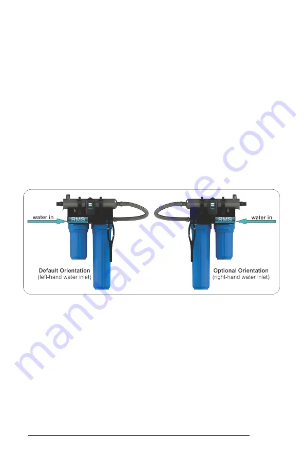
This system has the ambidextrous capability of being able to have the main water inlet enter 

from either the left hand side or right hand side of the unit. The units comes pre plumbed from 

the factory for a left hand water inlet. To change to a right hand water inlet follow these simple 

steps (See Figure 2):

Step 1:  Remove the blue filter sump housings (either one or two housings depending on the 

model purchased) from the filter head and set aside.

Step 2:  Remove the filter head screws from the top mounting plate (4 screws for a single filter 

model and 8 screws for a double filter model).

Step 3:  Carefully lower the filter head (or heads) from the rack assembly and rotate 180 de-

grees. Reassemble onto the rack assembly and take note of the arrows located on the top of the 

filter heads indicating water flow (which now should be indicating a flow direction of right-to-

left).

Step 4:  Remove the stainless steel UV reactor from the two plastic clamps located on the top 

of the rack. Carefully remove the top straps securing the reactor with the aid of a standard (slot) 

screwdriver). Rotate the reactor 180 degrees (with the inlet now facing to the left and the lamp 

connections located towards the right) and place back into the cell clamps and re affix the two 

top straps.

In either the left or right configurations, to facilitate lamp removal, ensure there is enough space 

at the lamp connector end to safely remove the UV lamp and/or quartz sleeve (See Figure 3).

Figure 2. System Orientation (water inlet)

Содержание RMS4-R1

Страница 1: ...ediment Carbon RMS4 R1 RMS5 R1 8 gpm YES 10 NO RMS4 R2 RMS5 R2 8 gpm YES 20 NO RMS4 R12 RMS5 R12 8 gpm YES 10 YES 20 RMS4 R2C RMS5 R2C 15 gpm YES 20 NO RMS4 R12C RMS5 R12C 15 gpm YES 10 YES 20 RMS4 R22C RMS5 R22C 15 gpm YES 20 YES 20 RMS5 R1 RMS5 R22C www rainwatermanagement com ...

Страница 2: ...upply with a UV system gives you reassurance that your family will have access to safe drinking water throughout your entire home with no chance of microbiological contamination This is chemical free process which is simple in its concept and effective in its abilities to inactivate microorganisms present in the water supply Simple maintenance continuous disinfection and ultimately safe water RMS ...

Страница 3: ... Operation 13 RMS4 Controllers 14 RMS5 RMS5 C Controllers 14 RMS5 RMS5 C Power up Sequence 14 RMS4 RMS4 C Operational Screens 15 RMS4 RMS6 Operational Screens 16 Lamp Countdown Sequence 16 Lamp Replacement RMS4 systems 17 Lamp Replacement RMS5 systems 17 QR Codes 17 System Troubleshooting 18 Temperature Management Devices 19 Expansion Modules 20 RMS Rack Mount UV System Specifications 21 Limited W...

Страница 4: ...rvice instructions if required 7 Do not use this system for any purpose other than what it was intended for Misuse of this system could potentially cause harm to the user or others 8 Your system is intended to be installed indoors and away from leaking plumbing DO NOT plug the unit in if the system or any of the components are wet 9 The disinfection system should be directly installed into a groun...

Страница 5: ...ent required will depend on parameters being treated Hardness 7 gpg 120 mg L if hardness level is 7 gpg or slightly below the quartz sleeve must be cleaned periodically in order to ensure effi cient UV penetration if above the water must be softened Iron Fe 0 3 ppm 0 3 mg L Manganese Mn 0 05 ppm 0 05 mg L Turbidity 1 NTU Tannins organics 0 1 ppm 0 1 mg L UVT transmittance 85 Please contact RMS if ...

Страница 6: ...S rack mount UV system is designed as a do it yourself DIY system with a single inlet and outlet port Unpack the system and ensure all the components are included in the box Your system is shipped with the following components ...

Страница 7: ...until the pump stops This is known as the cycle time 4 Then using a container of known volume preferably in US Gallons open the faucet or tap nearest the pressure system and measure the amount of water drawn off until the pump starts again Depending on the size of the container used it is acceptable to turn the faucet on and off to empty the container This measurement is known as the draw down To ...

Страница 8: ... plate 4 screws for a single filter model and 8 screws for a double filter model Step 3 Carefully lower the filter head or heads from the rack assembly and rotate 180 de grees Reassemble onto the rack assembly and take note of the arrows located on the top of the filter heads indicating water flow which now should be indicating a flow direction of right to left Step 4 Remove the stainless steel UV...

Страница 9: ...e residue on the sleeve and lamp which can ultimately block the UV light from getting to the water Carefully slide the sleeve into the reactor until you can feel it hit the opposite end of the reactor Align the sleeve so it centered along the length of the reactor then gently push it in to lock it into the internal centering springs in the far side of the reactor CAUTION Pushing too hard when the ...

Страница 10: ...e system The most common leak is from the o ring not making a proper seal on the reactor For new installations review steps 6 and 7 For older systems drain the reactor remove the o ring dry it and reapply silicon grease Reinstall the o ring ensuring that it is properly sealed against the reactor and check again for leaks To help vent the pressure from the system while the system is filling up with...

Страница 11: ...d turn the connector approximately turn to lock the connector to the gland nut as in Figure 10 Figure 9 Lamp Key Installation Figure 10 LUMI Loc Connector Step 14 Tighten the captive ground screw to the ground lug on the UV reactor to ensure proper grounding Figure 11 Ground Screw Connection Step 15 Your system is now ready to be plugged into the appropriate GFCI protected outlet Refer to the foll...

Страница 12: ...ing At a minimum the quartz sleeve should be cleaned on an annual basis The following steps outline a basic clean ing procedure Step 1 If a by pass assembly is installed shut the inlet valve off to prevent water flow through the system Otherwise turn off main water inlet valve and or turn off the water pump Step 2 Disconnect power cord of UV system from electrical outlet Step 3 Release water press...

Страница 13: ...y out of the sensor port Step 6 Holding the sensor in your hand wipe the flat portion sensor face of the sensor with isopropyl alcohol using a clean lint free cloth Step 7 Replace sensor following step 9 from the installation section of the manual Operation RMS systems come with a feature laden controller that incorporates both the lamp driver bal last and control features in one water tight case ...

Страница 14: ...er with a detailed description of the system s performance in addition to pro viding any applicable fault messages and system diagnostics The controllers used in both the RMS5 and RMS5 are iden tical The difference is that the RMS6series of products in cludes a UV intensity monitor All RMS5 RMS5 C controllers include an infinite expandability port located on the right side of the controller Simply...

Страница 15: ...d modules lamp reaching max output successful start up RMS5 RMS5 C Operational Screens On systems without the UV monitor the default screen shows the RMS Home Screen At any point during operation the user is able to scroll through the RMS Home Screen Lamp life re maining QR Code Contact Info and Maintenance Parts screens by pressing the button located on the front of the controller Rainwater Manag...

Страница 16: ...he screen is solid red and a constant audible alarm is given This alternates with a screen indicating water may be unsafe for consumption With the solenoid module the controller de activates the solenoid valve shutting off all water flow audible chirp every 15 seconds audible chirp every 15 seconds constant audible alarm cycles with red low uv screen Lamp Countdown Sequence The system counts down ...

Страница 17: ...countdown timer is then reset Lamp Replacement RMS5 RMS5 C systems After the lamp is expired it must be replaced with the same part number as indicated on the Maintenance Parts screen or on the label on the reactor With the system powered down re move and discard the lamp key from the controller The replacement lamp is packaged with a lamp key on the connector at the end of the lamp Remove the key...

Страница 18: ...l on the reactor or on the Maintenance parts screen Low UV Intensity Remove and clean the quartz sleeve and sensor Check water quality meets requirements on page 5 and add filtration as required Replace lamp Wrong lamp or sensor installed Replace component with proper model as indicated The UV sensor is no longer communicating to with the system Ensure all modules are connected properly to the sys...

Страница 19: ...ure Management Devices Your RMS RMS system is designed to run continuously to ensure optimal disinfection However during periods when no water is drawn through the system the energy from the disinfection process can cause the temperature of the water inside the chamber to rise In extreme situations elevated water temperature or the fluctuation in temperature can lower the output of the UV lamp In ...

Страница 20: ...ration the OK and COM contacts will be connected and in a fault condition Low UV Lamp fail Power Fail the Fault and COM contacts will be connected Maximum Contact Rat ing is 1A 120V AC DC use 16 22 AWG Order PN MOD RAM RMS SOLENOID CONNECTION MODULE Connects a NORMALLY CLOSED line voltage solenoid valve to the system On a non monitored system the sole noid will only close on a lamp failure error O...

Страница 21: ...0Hz Plug Type American NEMA 5 15P Lamp Power Watts 20 standard output lamp 45 high output lamp Power Watts 23 21 230V 57 48 230V Replacement Lamp RMS L420 RMS L420C Replacement Sleeve RMS Q420 Reactor Dimensions 8 9 x 50 8 cm 3 5 x 20 Chamber Material Polished 316L Stainless Steel A249 Pressure Rated Tubing Controller Dimensions 17 2 x 9 2 x 7 6 cm 6 8 x 3 6 x 3 21 8 x 10 7 x 8 9 cm 8 6 x 4 2 x 3 ...

Страница 22: ...at RMS manufactures RMS will not be liable for any costs of removal installation transportation or any other charges which may arise in connec tion with a warranty claim Products which are sold but not manufactured by RMS are subject to the warranty provided by the manufacturer of said products and not by RMS s warranty RMS will not be liable for damage or wear to products caused by abnormal opera...

Страница 23: ...EN IN LIEU OF ANY OTHER WARRANTY TO THE EXTENT ALLOWED BY APPLICABLE LAW ANY AND ALL EXPRESS OR IMPLIED WARRANTIES NOT SET FORTH HEREIN ARE WAIVED AND DISCLAIMED INCLUDING ANY IMPLIED WARRANTY OF MERCHANTABILITY OR FITNESS FOR A PARTICULAR USE RMS LIABILITY UNDER THIS LIMITED WARRANTY IS LIMITED SOLELY TO THOSE LIABILITIES SET FORTH ABOVE IN THE EVENT THAT ANY PROVISION OF THIS LIMITED WARRANTY SH...

Страница 24: ...Rainwater Management Solutions 2550 Shenandoah Ave NW Roanoke Virginia 24017 866 653 8337 www rainwatermanagement com PN 910300 Version Date 05 2019 ...

Отзывы: