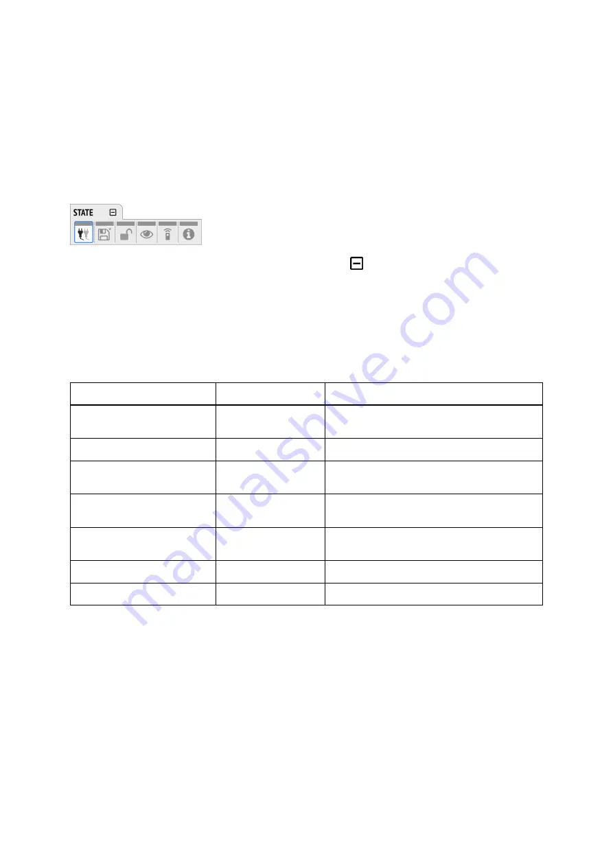
1. Rotate the encoder to highlight the "STATE" section
2. Rotate the encoder to highlight the "INPUT" section
3. Push the encoder to open the "INPUT" section.
2.2.2. Tabs
The
STATE
,
INPUT
and
OUTPUT
sections are further divided into
tabs
, which are shown when the
section is opened. Upon opening one of the four sections, a white cursor with a surrounding blue line is
shown to navigate between tabs and settings.
To close the section, move the cursor onto the minimize-icon
and confirm by pressing the encoder.
2.3. Status Indicator Color Chart
Notifications on this device have been optimized for different screen sizes. They are unified across the
device display and the web remote and feature a color bar that indicates the current state at a glance.
The following table shows the possible status indicator colors for reference.
Status
Color
Description
Warning
red
Requires a configuration change or matching
external signal.
Notice
yellow
There is a potential issue.
Notice (in progress)
yellow with dots
There is a temporary issue that should
resolve automatically.
No Routing
light green
In output section:
Output is sending an empty
signal.
Issues with Input
light green
On standby screen in output section:
Output is
working, but issues with input.
Good
green
Everything is working as expected.
Inactive
grey
Feature is not monitored or disabled.
RME M-32 DA Pro User’s Guide
2.3. Status Indicator Color Chart |
4
Содержание M-32 MIDI DA Pro
Страница 2: ...RME M 32 DA Pro User s Guide...


