Installation:
Unpack the amplifier from it’s shipping carton and inspect for any signs of damage. The
amplifier should be installed (either fixed or mobile installation), in a place that allows
good ventilation and provides a suitable base to support it. Failure to allow for reasonable
ventilation will cause the amplifier to overheat and damage may occur. A short 50 Ohm
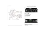
patch lead should be used to connect the amplifiers RTX SO239 input
[
connector to the
output, (Antenna Socket) of the drive Radio. This length of this cable is not critical but
should be of good quality and be kept as short as practically possible. The ANT output
]
connector of the amplifier should then be connected to antenna being used. (If an external
SWR/Power meter is to be used the amplifier should be connected to the input and then
the antenna to the output, This order of connection is very important. Check also that the
Antenna is suitably rated for the power output level. (Antenna SWR should not change
much from low to high power). The antenna should be tuned before connecting the pow-
er amplifier or with the amplifier switched OFF! .
In SSB mode the front panel switch
[
should be set to SSB. This adds a short delay to the
release time of the RTX relays so that pauses in speech do not cause the RTX relay to
drop out. In AM or FM mode the SSB delay switch should be set to AM.
The amplifier must be connected via the input power connector
\
to a suitable power sup-
ply of the correct voltage output and sufficient current rating. The output should be 13.6 /
13.8V DC but the amplifier may be connected to a supply from 12V to 14V DC without
damage. The current rating of the power supply must be at least 40A continuous. Be
aware that the current rating must be greater still if the drive radio is also connected to the
same power supply, although this is not generally advised.
The voltage output and current rating are very important for low voltage (12V) RF tran-
sistors as voltage sag, (poor load regulation) or insufficient current capability can drasti-
cally reduce the output power or cause distortion. If full output is not seen then the first
thing to check is that the voltage remains above 12.5V at full load. Anything less indi-
cates the power supply is not suitable for the amplifier at full output.
The cross sectional area of the cables used to connect the amplifier to the PSU should not
be less than 6mm² or 10 AWG. They should also be kept as short as practicably possible
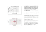
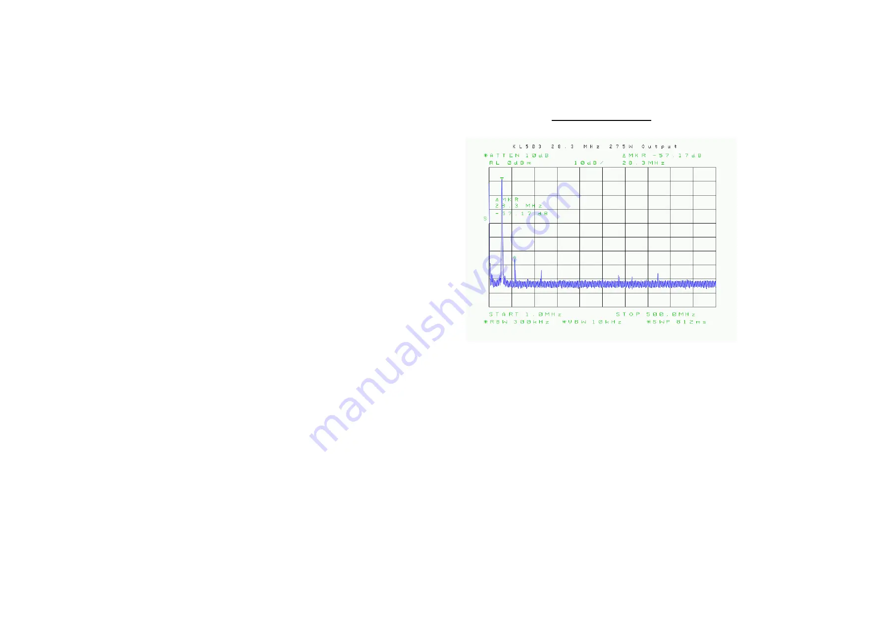
Typical Harmonic Output


