


HLA 305
3
3
2. Indice – Index
1
Introduzione – Introduction ............................................................................................................................................................................. 2
2
Indice
–
Index ................................................................................................................................................................................................ 3
3
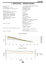
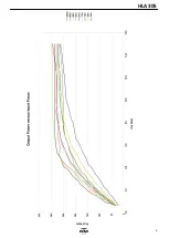
Specifiche - Specifications ............................................................................................................................................................................. 4
4
Descrizione parte Anteriore - Front panel description ..................................................................................................................................... 6
5
Descrizione parte Posteriore - Rear panel description .................................................................................................................................... 6
6
Italiano
....................................................................................... 7
6.1
Rimozione dall'imballo ed ispezione ............................ 7
6.2
Procedura d'installazione ............................................. 7
6.3
Connessione all’alimentazione .................................... 7
6.4
Antenna ....................................................................... 7
6.5
Massa ......................................................................... 7
6.6
PERICOLI ................................................................... 7
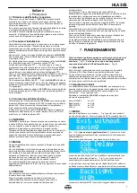
7
Funzionamento
......................................................................... 7
7.1
Uso in CW ................................................................... 7
7.2
Impostazioni iniziali ...................................................... 7
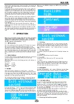
7.3
Menù
........................................................................... 7
7.3.1
SSB Delay ................................................... 7
7.3.2
Backlight High/Low ....................................... 7
7.3.3
Contrast ....................................................... 8
7.3.4
Exit ............................................................... 8
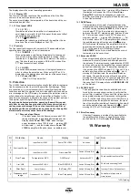
7.4
Operate ....................................................................... 8
7.4.1
Default Setting ............................................. 8
7.4.2
Visualizzazione stato amplificatore ............... 8
7.4.2.1
Display LCD .................................. 8
7.4.2.2
Indicazioni Lumisose ..................... 8
7.4.2.2.1
TX ................................. 8
7.4.2.2.2
A
WARNING ................ 8
7.4.3
Comandi ...................................................... 8
7.4.3.1
SSB/Off ........................................ 8
7.4.3.2
HI/Off ............................................ 8
7.4.3.3
Power ON/Off ............................... 8
8
Protezioni ................................................................................... 8
8.1
OVER Input Power .......................................... 8
8.2
OVER Temp ................................................... 8
8.3
SWR ............................................................... 8
8.4
FILTER FAULT ............................................... 8
8.5
Error Frequency .............................................. 8
9
Garanzia ..................................................................................... 9
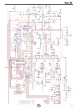
Schema elettrico .............................................................................12
Scheda per assistanza tecnica .......................................................14
16
English
Precaution ....................................................................9
16.1
Removal from packaging and inspection ....................9
16.2
Installation ..................................................................9
16.3
Connection to Power supply .......................................9
16.4
Antenna ......................................................................9
16.5
GROUND ...................................................................9
16.6
WARNING ..................................................................9
17
OPERATION .............................................................................10
17.1
CW Operation ............................................................10
17.2
Initial Settings .............................................................10
17.3
MENU ........................................................................10
17.3.1
SSB Delay ..................................................10
17.3.2
Backlight High/Low ......................................10
17.3.3
Contrast .......................................................10
17.3.4
Int VOX..........................................................10
17.3.5
Exit .............................................................10
17.4
Operate ......................................................................10
17.4.1
Default Setting ............................................10
17.4.2
Monitoring the Amplifier operation ...............10
17.4.2.1
Display LCD .................................10
17.4.2.2
Front Panel LED's ........................10
17.4.2.2.2
TX ................................10
17.4.2.2.3
A
WARNING ...............10
17.4.3
Front Panel controls ....................................10
17.4.3.1
SSB/Off .......................................10
17.4.3.2
HI/Off ...........................................11
17.4.3.3
Power ON/Off .............................11
18
Protection ..................................................................................11
18.1
Excessive Input Power ...............................................11
18.2
OVER Temp ...............................................................11
18.3
Excessive VSWR .......................................................11


