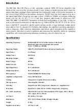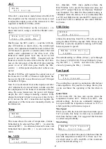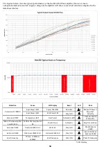
Dimmer
Adjust the brightness of the LCD back light between
two levels,
High
and
Low
. Default Setting is High.
Info
Selecting this menu displays the current ver-
sion of the firmware.
Default
This menu allows the user to return all parameters
back to factory default setting. Press OK, (
]
), to re-
store default settings.
ESC
Press OK, (
]
), to exit the menu system and return
the amplifier to Standby.
OPERATE
Switching Stby / ON, (
\
), to ON, switches the am-
plifier to Operate mode and the amplifier is now ac-
tive.
To use the amplifier it is sufficient to position the
switch AUT / MAN, (
_
), to AUT (Automatic band
filter selection), Ensure that the PTT, (
_
), is con-
nected from the output of the transceiver to the input
of the BLA350 Plus and that there is a suitable an-
tenna connected to the ANT, (
[
), output connector.
In this mode all of the functions of the amplifier are
fully automatic, When the PTT is pressed on the
transceiver, the amplifier will automatically measure
the input frequency and set the low pass band filter
accordingly. If the operator changes the operating
frequency the amplifier will automatically change the
band filter if required.
LCD Display (
[
)
The first row of the display shows the state of the
BLA350 Plus amplifier: Whether in Standby or Oper-
ate mode and whether the band filters are in Auto or
Manual selection mode. The second row shows the
temperature of the heat sink and the currently se-
lected Low Pass Filter.
Analogue Power Meter (
b
)
Displays the output power in Watts RMS.
Front Panel LED’s
ON (
c
)
Illuminates GREEN in Operate mode indicating that
the amplifier is ready to use.
TX (
d
)
Illuminates RED when the amplifier is in Transmis-
sion.
Warning (
e
)
Illuminates RED indicating that there is a problem
with the amplifier and the LCD Display (1) will re-
port the nature of the error.
MAN (
f
)
Illuminates YELLOW when the user has selected
manual filter selection. In this condition the user must
select the correct output filter. Failure to do so will
result in an error if the currently selected filter is not
suitable for the transmission frequency.
Front Panel Controls
All of the front panel controls should only be oper-
ated when the amplifier is not in transmission.
Stby / ON (
\
)
Switches the amplifier between Standby, (Stby), and
Operate, (ON), modes.
OK / SSB (
]
)
When in Standby mode pressing this switch the menu
list is accessed. Press repeatedly to cycle through the
menus. In Operate mode selects if the SSB Delay is
active or not when the Internal VOX is activated. (No
external PTT connected). When active the letter ‘
S
’ is
shown on the LCD display in the top right hand cor-
ner.
SET (
^
)
This switch is active only in Standby mode. It is used
to change parameters in the menu system.
AUT / MAN (
_
)
Allows the user to change between Automatic or
Manual Low Pass Filter selection. In manual mode
the filter is selected by rotating (
`
) to the desired fil-
ter.
MAIN ON / OFF (
a
)
AC mains power switch. When the amplifier is not in
use this should be set to OFF.
M E N U
D i m m e r
P u s h O K T o
R e s t o r e D e f a u l t
O p e r a t e A u t o
T
: 2 8
° C B
: 1 0
-
1 2
m
O p e r a t e A u t o
T
: 2 8
° C B
: 1 0
-
1 2
m
O p e r a t e A u t o S
T
: 2 8
° C B
: 1 0
-
1 2
m
8
Содержание BLA350 PLUS
Страница 2: ......


