background image

17.3.1.6 

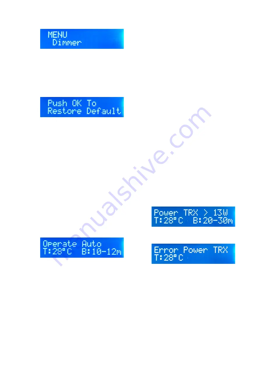
Dimmer

It is possible to adjust the brightness of the LCD back 
light between two levels.
17.3.1.6.1 

High

default
17.3.1.6.2 

Low

1

7.3.1.7 

Info

Selecting this menu displays the current version of the installed 
firmware.
17.3.1.8 

Default

This menu allows the user to return all user software changes 
to that of the default factory condition.

17.3.1.8.1 

Restore default

Pressing OK restores all data to default factory 
supplied values.

17.3.1.9 

ESC

Pressing OK exits the menu system and returns the amplifier to 
Standby.

17.4 

OPERATE

Moving the switch 

Stby/ON

 to 

ON

 enters the mode 

Operate 

and the amplifier is active.

1

7.4.1 

Default setting

To use the amplifier immediately it is sufficient to position the 
switch (

_

for the selection of the band pass filters to AUT, 

(Automatic). Ensuring that PTT (

_

)

 input is connected from the 

transmitter, the antenna is connected to the ANT (

[

) connector 

and that it is suitable for the desired frequency of operation and 
power rating. In this mode all of the functions of the amplifier 
are completely automatic and no operator intervention is 
required. 
If all menus remain at their default settings when operating the 
transceiver in TX the amplifier will automatically measure the 
input frequency and select the correct band filter. If the operator 
changes the transmit frequency the microprocessor will 
automatically change to the correct band filter if necessary. 
17.4.2 

Monitoring the Amplifiers operation


It is possible to monitor many of the amplifiers parameters 
during operation and the operator may choose which 
parameters they wish to see displayed. 
17.4.2.1 

Display LCD

The display shows:

On the first row is displayed the state of the amplifier. 
The second row displays the temperature of the heat sink and 
the  current selected output filter.  
17.4.2.2 

Analogue panel meter


17.4.2.2.1 

Output power 

(

b

)

This indicates the output power in Watts (RMS)

17.4.2.3 

Front panel LED's

17.4.2.3.1 

ON

 (

c

)

Illuminates green in Operate mode and indicates 
amplifier is ready to use.
17.4.2.3.2 

TX 

(

d

)

Illuminates red when the amplifier is in transmission.
17.4.2.3.3 

A

 WARNING 

(

e

)

Illuminates red indicating a problem with the amplifier, 
the description of the error is displayed on the LCD.
17.4.2.3.4 

MAN 

(

f

)

Illuminates yellow when in manual filter selection 

mode.

17.4.3 

Controls 

The front panel features several user controls. These should 
only be operated when the amplifier is not in transmission.

17.4.3.1 

Stby/ON 

(

\

)

Switches the amplifier between Standby (Stby) and 
Operate (ON) modes.
17.4.3.2 

OK/SSB

 (

]

)

This switch allows entry to the menu system in 
Standby mode. Or in Operate mode selects if the 
SSB delay is active or not when used with the internal 
VOX. When inserted an 'S' is displayed on the LCD 
top right hand corner. 
17.4.3.3 

SET 

(

^

)

Active only in Standby mode. Allows user to change 
parameters in the menu system.
17.4.3.4 

AUT/MAN

 (

_

)

Allows user to change between Automatic and 
Manual selection of the LPF's (Low Pass Filter). In 
manual mode filter selection is made with (

`

).

17.4.3.5 

MAIN ON/OFF

 (

a

)

AC Mains power switch.

18. 

Protection

The BLA350 features several sophisticated protection circuits 
that will interrupt operation if necessary in order to protect the 
amplifier from damage. These are controlled by a powerful 
microprocessor that can identify all possible fault conditions and 
alert the operator  with either an  audible error tone or by means 
of a error message on the the LCD display. If necessary the 
protection circuits will shut down the amplifier and return the 
amplifier to Standby. In this case it will be necessary to 
eliminate the cause of the problem and reset the amplifier by 
switching the AC supply off and on. (

a

) or switch Stby/ON (

\

).

Despite sophisticated protection, operating the amplifier 
repeatedly after an error has been reported without any 
correction may cause permanent damage.  The use of an 
incorrect band filter or transmitting without a suitable 
antenna connected to the amplifier at maximum power may 
cause irreversible damage.


18.1 

Excessive Input Power

If the input power from the transceiver rises above 13W  the red 

A


warning LED will illuminate (

e

) and the display shows:

 If the input power then rises above 15W the amplifier will be 
shut down, an audible error tone will be emitted and the 

A


warning LED will remain illuminated. In this case the LCD will 
show:

 It will then be necessary to restart the amplifier by switching the 
amplifier off and then back on to reset the protection. 

18.2

 OVER Temp.

The temperature at the point of contact between the transistors 
and the heat sink regulates the speed of the heat sink cooling 
fan. If the temperature is below 35°C the fans are off, (in Quiet 
mode), between 40 and 55°C the fans turn at minimum speed, 
between 55 and 65°C medium speed (also set from menu 
17.3.1.3.3), between 65 and 75 °C the speed is high. Above 
75°C the speed is maximum and an audible tone is sounded 
and the  

A


warning LED illuminates (

e

 par.4). If the 

temperature increases above 80°C the amplifier will shut down, 
the audible warning will continue and the 

A

 warning LED will 

remain illuminated. The amplifier will return to normal operation 
when the temperature drops below 60°C.
In the above case the LCD Display will show: 

OVER TEMP! 

on 

-14-

Содержание BLA 350

Страница 1: ... 1 Amplificatore Lineare per bande HF a stato solido Solid State HF Linear Power Amplifier BLA 350 Manuale Utente User Manual 3Costruzioni Elettroniche S n c http www rmitaly com ...

Страница 2: ...iù performante ed eviterà errori che oltre a causare una perdita di potenza in uscita potrebbero determinare danni ai componenti anche in maniera irreversibile Un uso attento e corretto vi farà apprezzare le performance del BLA 350 per molti anni senza nessun intervento tecnico Introduction The BLA 350 Linear Amplifier is a high performance amplifier designed for use with all HF transceivers and a...

Страница 3: ...Delay 9 7 3 1 4 1 Delay set 9 7 3 1 5 Fan Speed 9 7 3 1 5 1 Quiet mode 9 7 3 1 5 2 Max Speed 9 7 3 1 5 3 Man Setting 9 7 3 1 6 Dimmer 9 7 3 1 6 1 High 9 7 3 1 6 2 Low 9 7 3 1 7 INFO 9 7 3 1 8 Default 9 7 3 1 8 1 Restore Default 9 7 3 1 9 Esc 9 7 4 Operate 9 7 4 1 Default Setting 9 7 4 2 Visualizzazione stato amplificatore 9 7 4 2 1 Display LCD 10 7 4 2 2 Strumento Analogico 10 7 5 2 2 1 OUTPUT POW...

Страница 4: ...ng 13 17 3 1 6 Dimmer 14 17 3 1 6 1 High 14 17 3 1 6 2 Low 14 17 3 1 7 INFO 14 17 3 1 8 Default 14 17 3 1 8 1 Restore Default 14 17 3 1 9 ESC 14 17 4 Operate 14 17 4 1 Default Setting 14 17 4 2 Monitoring the Amplifier operation 14 17 4 2 1 Display LCD 14 17 4 2 2 Analogue panel meters 14 17 4 2 2 1 OUTPUT POWER 14 17 4 2 3 Front Panel LED s 14 17 4 2 3 1 ON 14 17 4 2 3 2 TX 14 17 4 2 3 3 A WARNIN...

Страница 5: ...push pull Metodo di raffreddamento Cooling Method Forced Air Cooling Microprocessore MPU PIC 18F4620 Strumenti Meters Potenza d uscita Output Power 600 W Temperatura dissipatore Heat sink temperature Stato amplificatore Amplifier state Banda usata Used band Protezioni Protection Potenze d ingresso Input Power Errore Filtri Error Filter R O S S W R Temperatura Temperature Frequenza Frequency Connet...

Страница 6: ...rm fault conditions 12 MAN Illuminates when the band selection is in manual mode 1 Display LCD Visualizza i parametri di funzionamento 2 Standby ON Interruttore di attivazione dell amplificatore 3 OK SSB Pulsante conferma impostazione inserimento ritardo SSB 4 SET Pulsante navigazione Menù 5 AUT MAN Seleziona il modo di selezione dei filtri passa basso 6 BAND Selezione manuale del filtro di banda ...

Страница 7: ...rno al BLA 350 che fornisce il segnale necessario per un miglior controllo della commutazione si consiglia in ogni caso l uso dell ingresso PTT Entrambi i connettori sopra menzionati sono di tipo RCA Usare un corto spezzone di cavo coassiale tipo RG 58A U o RG 8A U o equivalenti per l interconnessione dell uscita del ricetrasmettitore al connettore RTX del BLA 350 Per la connessione dell uscita AN...

Страница 8: ...abbrica con una adeguata strumentazione la loro modifica fa decadere la garanzia 7 FUNZIONAMENTO Prima di iniziare qualsiasi operazione verificare che la tensione di rete presente alla presa d alimentazione corrisponda alla tensione nominale scritta sull adesivo posteriore b Verificare che un antenna adeguata sia connessa al connettore ANT dell amplificatore 7 1 Uso in CW Dato il tempo di commutaz...

Страница 9: ...silenzioso fino al raggiungimento dei 55 C 7 3 1 5 2 Max Speed premendo OK le ventole vengono attivate alla massima velocità per 5 secondi permette la pulizia delle ventole e del dissipatore Menù da utilizzare periodicamente per effettuare la pulizia 7 3 1 5 3 Man setting E possibile variare la velocità delle ventole al raggiungimento dei 55 C tra 9 passi circa dal 20 al 80 della velocità di defau...

Страница 10: ...re L uso con un filtro di banda errato o senza un antenna collegata può essere distruttivo se è operato alla massima potenza 8 1 OVER Input Power Se la potenza di ingresso all amplificatore supera i 13W lampeggia l indicazione rossa A dell indicatore WARNING e e sul display viene scritto Power TRX 13W Se la potenza d ingresso supera i 15W il lineare viene bloccato l operatore sentirà l allarme aud...

Страница 11: ... notificarlo immediatamente al rivenditore inviandogli copia del Repair Form correttamente compilato Una eventuale sostituzione dell amplificatore può avvenire solo ad insindacabile giudizio di 3 non oltre il decimo giorno di ricezione del prodotto La garanzia sarà riconosciuta solo se il prodotto è accompagnato dalla copia del documento di acquisto se il serial number è leggibile se il prodotto r...

Страница 12: ... case that the antenna does not correspond to this it will be necessary to use a system of impedance matching such as an antenna tuner to provide the correct impedance transformation If using such a device it must be capable of withstanding the output level of the amplifier otherwise damage to the matching device and or the amplifier may result 16 5 GROUND This amplifier must be connected to the R...

Страница 13: ...thout the amplifier in transmission Use your transceiver in CW or FM mode at maximum output power the input power to the amplifier can be seen on the LCD display transmit and at the same time adjust with the ALC trimmer on the rear panel until the display reads 12W then press OK Now every time the amplifier is set in OPERATE mode the ALC circuit will automatically limit the output power of the tra...

Страница 14: ...modes 17 4 3 2 OK SSB This switch allows entry to the menu system in Standby mode Or in Operate mode selects if the SSB delay is active or not when used with the internal VOX When inserted an S is displayed on the LCD top right hand corner 17 4 3 3 SET Active only in Standby mode Allows user to change parameters in the menu system 17 4 3 4 AUT MAN _ Allows user to change between Automatic and Manu...

Страница 15: ...sportation duties and insurance between the purchaser and RM Italy or an RM Italy approved service centre are the responsibility of the purchaser both to and from the service centre The warranty must be requested to the distributor or reseller where the amplifier was originally purchased In the case where the original distributor or reseller no longer exits or no longer deals with RM Italy product...

Страница 16: ... Level then OK Temp Celsius Fahrenheit Int VOX Disabled Enabled SSB Delay 0 ms 100 ms 250 ms 500 ms 750 ms 1000 ms Fan Speed Quiet mode ON OFF Max Speed Man Setting 5 ô 1 9 Dimmer High Low Info Firmware info Default Restore Default ESC ...

Страница 17: ... 17 ...

Страница 18: ... 18 ...

Страница 19: ... 19 ...

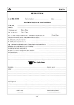
Страница 20: ... not set to maximum power what is the maximum value What band does the fault occur What is the transmission mode How long does the amplifier operate normally before the fault occurs Is there an error message on the LCD Display What is the heat sink temperature What was the mains voltage at the time of fault Other information 3 Technician Technician Date of repair Notes Parts replaced Date of test ...

Отзывы: