la potenza d'ingresso supera i 12-13 W viene automaticamente inserito l'attenuatore di -3dB
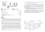
(visualizzato dall'accensione del led verde
d
d
d
d
d
), se la potenza sale ancora a 25W avviene
l'esclusione dell'amplificatore indicando lo stato di protezione con l'accensione del led rosso
d
d
d
d
d
.
Al suo interno ha installata una ventola per dissipare con maggior efficienza il calore prodotto.
La ventola funziona a velocità variabile per ridurre la rumorosità in ricezione quando il suo uso
è meno necessario.
INSTALLAZIONE
Dopo aver tolto l'amplificatore dal suo imballo ed aver controllato che non abbia subito
danni durante il trasporto, collegare, con una prolunga di RG58 lunga circa 90 cm., il
ricetrasmettitore al connettore SO239 siglato con RTX (
i
) e l'antenna al connettore ANT (
h
)
posti entrambi sul lato posteriore dell'amplificatore, assicurarsi che l'interruttore di accensione
(
f
) sia in posizione OFF, collegare il cavo di alimentazione fornito in dotazione alla spina
posteriore (
g
) assicurandosi che sia inserita completamente, l'altra estremità dovrà essere
inserita in una appropriata presa di rete.
Per il corretto funzionamento dell'amplificatore, si consiglia di utilizzare anche le connessioni
ALC (
j
) e PTT (
k
), connettendole alle corrispondenti connessioni del trasmettitore
Posizionare sempre l'amplificatore in modo da poter accedere con facilità a tutti i comandi
avendo cura di lasciare spazio intorno ad esso per permettere una buona ventilazione.
ATTENZIONE !!!
Prima dell'utilizzo dell'amplificatore verificare che antenna e alimentazione
abbiano caratteristiche adeguate.
USO
Accendere l'amplificatore tramite l'apposito interruttore (
f
), posizione ON, si noterà l' illumi-
narsi del wattmetro
e
.
Posizionare i comandi come è necessario considerando che:
Il deviatore
_
inserisce o disinserisce l'attenuatore d'ingresso, se l'attenuatore è inserito
si accende l'indicatore
d
di colore verde. L'attenuatore varia di circa 3 dB il livello di potenza
di pilotaggio dello stadio di potenza permettendo di migliorare la resa dell'amplificatore . In caso
il segnale in ingresso sia superiore ad 12 W (20 PEP) l'attenuatore si inserisce automaticamente.
L'interruttore
]
se posto su
SSB Delay
inserisce un ritardo di circa 1- 1,5 sec. al rilascio
del relè d'antenna per luso in SSB o CW, se è utilizzato l'ingresso
PTT
posteriore (
j
), connesso
alla relativa presa sul ricetrasmettitore (modo consigliato), l'interruttore
]
deve essere in
posizione
OFF
.
Il selettore dei filtri Passa-basso (
`
) deve essere posto sulla frequenza immediatamente
superiore alla frequenza di trasmissione, cioè 2MHz per 160m, 4MHz per 80m. 7,5 MHz per 40m,
15 MHz per 30 - 20m, 22 MHZ per 17 - 15m, 30 MHz per 12-10m.
Se viene selezionata una banda sbagliata quando si commuta in trasmissione si verificano due
Before using the amplifier check antenna and alimentation to have some appropriate
characteristics.
USAGE
Switch the amplifier through (
f
), ON position. The wattmeter (
e
) will light up.
Put the controls as it is necessary, considering that:
The switch
_
connects or disconnects the input attenuator. If the attenuator is
connected the indicator
d
will light up of green. Moreover the attenuator changes of 3 dB
the level of pilot power, permitting to improve the amplifier yield. In case of input signal is higher
than 12 W (20 PEP), attenuator is connected automatically.
If the switch
]
is placed on
SSB Delay,
it inserts a delay of about 1-1,5 sec. at antenna
relay release for the use in SSB CW. If it is used the posterior PTT input (
j
) connected to the
relative plug on the two-way radio (advised way), the switch
]
must be on OFF.
The low-pass filter selector (
`
)
must be placed on the frequency just superior to the
transmission one, that is 2MHz for 160m, 4MHz for 80m. 7,5 MHz for 40m, 15 MHz for 30 - 20m,
22 MHZ for 17 - 15m, 30 MHz for 12-10m.
In case of wrong band selection when it is commutated in transmission, two situations
can happen:
1.
If a filter with an excessive
quench frequency is used, one or more harmonic
frequencies of transmission frequency may be emitted; however this doesn’t damage
the amplifier.
2.
If the transmission frequency is greater than the quench one the amplifier protection
circuit intervenes (red led
d
d
d
d
d
ignition), preventing the commutation in transmission.
The switch
^
^
^
^
^
permits linear amplifier ignition.
The switch
\
\
\
\
\
permits antenna preamplifier ignition.
Antenna preamplifier is independent from linear amplifier working.
For a good working, with a low level of intermodulation from the strong signals
present in HF, preamplifier is made of a circuit tunable trough the control
[
. For the use
it is necessary to have a signal in antenna, even just audible, on the use frequency or on
a near one (preamplifier is on off). Then switch the preamplifier and tune it by the control
[
,
up to the point of maximum intelligibility signal.
When the amplifier is in transmission the indicator
TX
(
b
) lights up and outlet power
is indicated through the instrument (
e
).
Protection
indicator (
d
) lights up (red) only if there is a danger condition for amplifier
integrity. The possible causes are:
1.
selection of a filter for a frequency which is inferior to that usage one
2.
excessive level of stationary waves (ROS) in antenna.
Check the filter arranged through the commutator
`
or ROS level in antenna before
continuing with the amplifier use.
For restoring the normal usage of the amplifier switch on and then switch off
^
^
^
^
^
.


