


6 Operation
Rittal air/water heat exchanger assembly instructions
17
EN
While in programming mode, if you do not press any
buttons for approx. 30 sec., the display will first flash,
then the controller will switch back to normal display
mode. The “Esc” display indicates that any changes
made have not been saved.
Press the programming buttons
▲
(°C) or
▼
(°F)
to switch back and forth between the editable
parameters (see tables 5 and 6).
Press button 2 (“set”) to select the displayed
parameter for editing.
The current value of this parameter is displayed.
Press one of the programming buttons
▲
(°C)
or
▼
(°F).
The “Cod” display will appear. In order to be able to
change a value, you must enter the authorisation
code “22”.
Keep the programming button
▲
(°C) held down
until “22” appears.
Press button 2 (“set”) to confirm the code.
You can now alter the parameter within the preset
limits.
Press one of the programming buttons
▲
(°C)
or
▼
(°F) until the required value appears.
Press button 2 (“set”) to confirm the change.
You can now alter other parameters in the same way.
There is no need to re-enter the authorisation code
“22”.
To exit programming mode, press button 2 (“set”)
again for approximately 5 seconds.
“Acc”
will appear in the display to indicate that
the changes have been saved. The display then
switches back to regular operation (enclosure inter-
nal temperature).
You can also program the e-Comfort controller
using a diagnosis software package (Model No.
3159.100), the supply of which also includes
a connection cable to the PC. The cable connector
on the rear of the e-Comfort controller display serves
as an
interface.
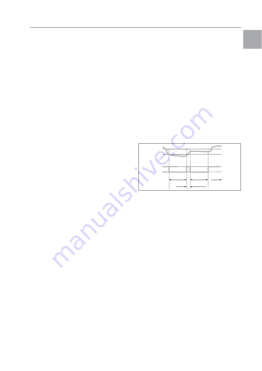
6.2.4 Eco-mode
All Rittal TopTherm heat exchangers with e-Comfort
controller from firmware 3.2 have the energy-saving
eco-mode, which is activated in the delivered state.
The eco-mode is used to save energy in the heat
exchanger if there is no thermal load, or there is a low
thermal load in the enclosure (e.g. standby opera-
tion, no production or weekend). During this process
the heat exchanger fan in the internal circuit is
switched off as appropriate if the actual enclosure
internal temperature drops to 10 K below the setpoint
temperature set. Also to reliably measure the inter-
nal temperature during this process, the fan starts
cyclically for 30 sec. every 10 minutes (see fig. 21).
If the internal temperature reaches the range 5 K
below the setpoint set again, the fan switches back
to continuous operation. If required, the eco-mode
can be deactivated via the control display. For this
purpose switch the parameter from 1 to 0 in the
programming level (see tab. 8, page 18). The fan
then runs continuously.
Fig. 22:
Diagram of eco-mode
ON
Internal
fan status
Internal
temperature
Time
Setpoint
–5 K
Setpoint
–10 K
OFF
10 min.
30 sec.
10 min.


