background image

3

Prepare a Foundation for Your Greenhouse

Before assembling your new Greenhouse a proper foundation must be prepared. A number of anchoring 

options are possible, based on wind and ground conditions in your area.
Make sure that you have checked with your local authorities regarding any required building permits.
Decide at this time the final orientation of your Greenhouse. We recommend that you place your greenhouse 

in a spot where it will receive direct sunlight and will be protected from the wind as much as possible. The door 

should not face prevailing winds.
It is important to clear your Greenhouse of snow in the winter.

Note: 

You may assemble the greenhouse on its base on a hard surface and move it to its final position when 

you have finished. Make sure that there are no obstructions between the assembly area and the final position.

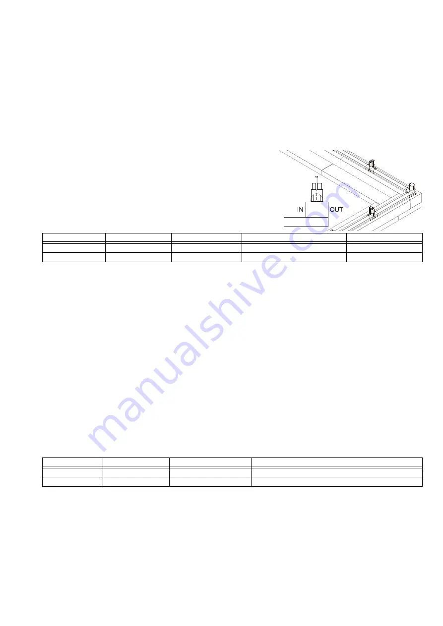
Treated Wood Base

Build a framework composed of 4 

×

 6 (

1

) and 2 

×

 12 (

2

) treated 

lumber using deck screws or galvanized lag bolts and fill it with 

gravel or earth or other suitable material to fill the base up to the top 
surface of the 4 

×

 6 (

1

). Attach the greenhouse frame through the 

connectors using screws that are 6 mm (

B

") in diameter and no less 

than 70 mm (2

C

") long (not supplied).

Wood Deck

Your Greenhouse can be secured to a wood deck with screws (not supplied) through the frame connectors. Use 

screws that are 6 mm (

B

”) in diameter and no less than 70 mm (2

C

“) long. Make sure that the wood deck 

itself is securely anchored to the ground. See hardware quantities and foundation measurements above.

Excavated Trench

Your Greenhouse can be placed in an excavated trench to anchor it to the ground. See the foundation 

measurements above for dimensions.

Concrete Foundation

Prepare a poured concrete foundation according to local building codes. Do not excavate and pour concrete in 

frozen ground. Make sure that there is a slight slope for drainage.
Pour your foundation according to the size of the greenhouse model you have selected. Make sure that the 

foundation is at least 10 cm (4") larger than the size of the greenhouse. The Greenhouse is secured to the 

concrete foundation using screws and concrete anchors or expansion anchors (not supplied). Use screws 6 mm 

(

B

") in diameter and no less than 70 mm (2

C

") long. A drill with an appropriate masonry bit is required.

Model

Base Width

 Base Length

Fill Quantity

Screw/Lagbolts

ECO 1/2

2.03 meter (6’ 7

G

”)

2.36 meter (7’ 7

G

”)

0.78 cubic meters

 (27.5 cubic feet)

20

ECO 1/2 + Middle

2.03 meter (6’ 7

G

”)

3.10 meter

 (10’ 2H”)

1.16 cubic meters

 (41 cubic feet)

24

Model

Foundation Width

Foundation Length

Screw/anchor set or expansion anchor

ECO 1/2

2.07 meter (6’ 9")

2.41 meter (7’ 10

G

")

20

ECO 1/2 + Middle 2.07 meter (6’ 9")

3.15 meter (10’ 4")

24

2

1

1

2

Содержание Eco Greenhouse EcoGrow

Страница 1: ...EcoGrow Assembly Instructions...

Страница 2: ...N S W 2560 61 2 4627 0777 Fax 61 2 4627 0999 sales oldfields com au http www oldfields com au treco index htm Germany Clemens HobbyTec GbR Rudolf Diesel Str 8 D 54516 Wittlich Germany 49 0 6571 929 22...

Страница 3: ...rect sunlight and will be protected from the wind as much as possible The door should not face prevailing winds When your Greenhouse is fully assembled examine it for sharp edges and trim with a razor...

Страница 4: ...wish to disassemble the parts at any time remove the pins using the pin tool Place the end into the exposed hole and lever the pin out 4If a hole in the connector is missing drill a hole with a 6 mm...

Страница 5: ...e can be secured to a wood deck with screws not supplied through the frame connectors Use screws that are 6 mm B in diameter and no less than 70 mm 2C long Make sure that the wood deck itself is secur...

Страница 6: ...parts are missing The part code is stamped on each connector Profiles are listed in order by size largest to smallest Panels are identified with stickers Some glazing elements RA RB RC and RD are plac...

Страница 7: ...Oval Profile 39 4 cm 1 3A E5 4 0 Oval Profile 13 4 cm 5B E72 15 5 Oval Profile 65 8 cm 2 1G SR1 1 0 Inner Round Profile 40 cm 1 3C DoorW1 1 0 Door Handle Connector D1 2 0 Side Cap D2 2 1 Middle Cap P...

Страница 8: ...ediment Panel option 59 7 44 7 cm 1 11A 1 5F WIN34 1 0 Roof Vent WINH31 2 0 Roof Vent Handle DSN 1 0 Door Sealer roll RA2 3 1 Bottom Roof Glazing 69 3 cm 2 3B RB1 12 4 Roof Glazing 52 cm 1 8A RB3 4 0...

Страница 9: ...the Door22 door hinge 3 Attach the Door22 hinge under a 2D connector with two AS80 lower hinge bolts and then snap the 2D connector and hinge to the left side of the prepared B2 frame profile Note Arr...

Страница 10: ...to its final position when you have finished Make sure that there are no obstructions between the assembly area and the final position Wood Deck or Treated Foundation Insert screws into the frame con...

Страница 11: ...d door pediment with the 7A connector and the R3 profile taking advantage of the flexibility of the profiles 4 Lock the pediment in place using pins and remove the ID strips from the panel Complete Do...

Страница 12: ...lide the three panels in place Make sure that the plastic ID strip faces the outside 4Assemble the lower profiles and connectors and complete the back pediment taking advantage of the flexibility of t...

Страница 13: ...pins 3 Assemble the rest of the arches according to the number of ECO middle sections you have purchased 4 Add E72 profiles to the front pediment 5 Lock the parts in place using pins 6 Add E72 profil...

Страница 14: ...f the roof 2Place RA2 glazing elements on the top of the roof by placing one end in the top channel and pushing it down along the length of the profile 3Place RB1 and RB3 glazing elements along the ar...

Страница 15: ...downwards 2 Place each PN76 and PN78 panel in place by sliding one corner into the RD3 glazing element and then continue until it is fully inserted and lying flat Make sure that the plastic ID strip...

Страница 16: ...the RC glazing elements are in line with the bottom of the RD elements 2Finish locking the panels into place by placing RC10 glazing elements across the top of the roof 3 Remove the ID strips from th...

Страница 17: ...enters the upper RD3 element 3 Continue with the rest of the PN75 and PN77 panels 4 Lock the lower panels into place using RC1 glazing elements Make sure that the end of the RC glazing elements are i...

Страница 18: ...that the plastic ID strip of a PN 70 panel faces out and put it in place by gently curving it so that it enters the side channels of the columns 5Lower the panel towards the frame and slide it into t...

Страница 19: ...frame Lift the roof from both edges and walk through the door towards the back wall 2 Place the roof on the columns and circle around the greenhouse and insert the first 1 cm of the roof connectors i...

Страница 20: ...Holder through the E2 profile in the pin hole on the side of the DoorW1 connector Note The larger handle always faces the outside 4Assemble the upper portion of the door Put the PN61 panel in place w...

Страница 21: ...n so that the pin enters the corresponding hole in the door 6 Secure the door to the upper door lintel by screwing in the second AS80 screw and wingnut through the pinholes 7 Screw the Dow2 Door Holde...

Страница 22: ...if necessary It is important to clear your Greenhouse of snow in the winter If you live in a hot climate where outside temperatures exceed 46 C 115 F in the sun or 36 C 99 F in the shade this may caus...

Страница 23: ...21 Notes...

Страница 24: ...Rev 5032008...

Отзывы: