- 22 -
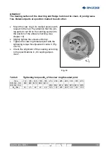
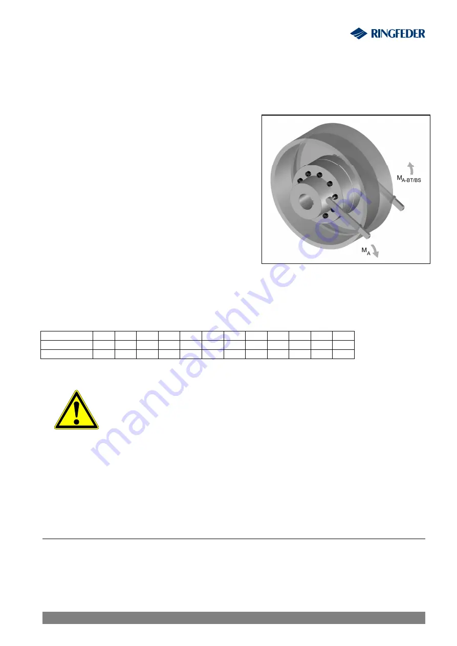
Fig. 14
10.4 Assembly brake drum/disk
Attention!
The contact surfaces of coupling hub and brake drum/disk must be clean, dry and free
of grease. Balanced parts are match marked to each other.
·
Place the brake drum/disk in their proper
position as marked. Make sure that the parts do
not get canted at the centering seats when join-
ing them.
·
Slightly tighten the screws.
·
Tighten the screwed connections of brake
drum/disk to the proper torque M
A
specified in
table 10.
·
Check the alignment of the coupling according
to the instructions given in chapter 8 ‘Coupling
Alignment“.
Table 10
Tightening torques M
A-
for brake drum/disk threaded joints:
Size
112 128 148 168 194 214 240 265 295 330 370 415
DIN 933- 8.8
8
8
10
10
12
12
12
16
16
16
16
16
M
A-BS
[Nm]
25
25
49
49
85
85
85 210 210 210 210 210
Warning!
§
Before commissioning the plant install all protective devices
against unintentional touching of free rotating parts.
§
To avoid sparks coverings in stainless steel should be used.
§
The coverings must fulfil at least the protection type IP2X.
§
The covering is to be so designed that it does not deposit dust
onto the coupling parts.
§
The covering must not touch the coupling or influence it in its
functioning.
When using accessories and spare parts which were not originally manufactured by
RINGFEDER POWER TRANSMISSION, no liability or guarantee for any damages
will be accepted.
11 Waste Disposal
The waste disposal has to occur according to the specific regulations of the respective user
country.
RINGFEDER
®
TNM GBT, TNM GTW
BAWN 006-
GBR
-1


