background image

9

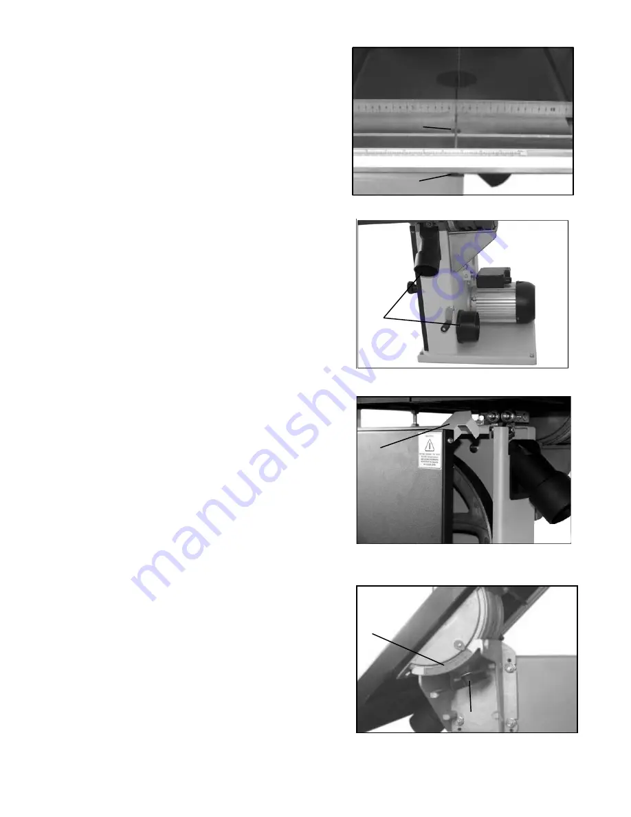
Dust Extraction

The machine is equipped with two dust extraction
ports, 4" and 2.5". (See Fig.14 B)

It is recommended that when in use, the machine is
connected to a suitable dust collector which should
be able produce an air speed of approximatley
350 CFM through the dust port areas.

Lower Blade Guard

When opening the lower band-wheel door on this
machine, the


lower blade guard (C)


swings down.

(See Fig.15)

When the lower door is closed, the guard MUST be
raised back to its operating position.

The band-wheel doors MUST be closed at all times
when the machine is being operated.

Tilting the Bandsaw Table

Ensure the table is clear of loose objects. Loosen
the wing nut (D) on the lower trunnion, then tilt the
table to the angle required using the scale (E)

.

(See Fig.16)

When the required setting is reached, re-tighten the
wing nut to lock the table into position.

Fig. 13

Fig. 14

Fig. 15

Fig. 16

B

C

E

D

Checking the Table for Flatness

Once the scale is set to the desired position the
table should be checked for flatness. This can
be done by using a steel rule as a straight edge.

The steel rule should be held on the table across
the table slot close to the front edge of the table.
(See Fig.13)

If the straight edge shows there is a step across
the table slot, then the table needs to be
adjusted using the Hex socket screw (A) and
wing nut (B) to level the two sections.
(See Fig.13)

A

B

Содержание 10-320

Страница 1: ...rikontools com or info rikontools com For Parts or Questions techsupport rikontools com or 877 884 5167 Record the serial number and date of purchase in your manual for future reference Serial number...

Страница 2: ...LCOHOL ALWAYS WEAR PROPER APPAREL Never wear loose clothing or jewelry that might get caught in moving parts Rubber soled footwear is recommended for the best footing ALWAYS USE SAFETY GLASSES AND WEA...

Страница 3: ...VER LEAVE TOOLS RUNNING UNATTENDED 1 Always stop the Bandsaw before removing scrap pieces from table 2 Always keep hands and fingers away from the blade 3 Never attempt to saw stock that does not have...

Страница 4: ...ank Handle 7 Assembling the Optional Rip Fence 7 Adjustments 8 Centering the Table to the Blade 8 Setting the Table Square to Saw Blade 8 Checking the Table for Flatness 9 Lower Blade Guard 9 Tilting...

Страница 5: ...PANEL 1 12S REAR ANGLE BAR 1 5S RIGHT END PANEL 1 13S PAN HEAD SCREW 2 6S BACK PANEL 1 14S SELF LOCK NUT 2 7S HEX SET SCREW 1 4 x20x7 8 24 15S SHELF 1 8S HEX NUT 1 4 x20 28 Assemble base cabinet as s...

Страница 6: ...nderside of the bandsaw table D using the four M8 x 16 hex head set screws E and washers ensuring that the angle tilt scale is closest to the edge of the table See Fig 03 While the table is in the ups...

Страница 7: ...the fence body accordingly Correcting for Blade Drift Loosen the two hex head screws which hold the fence rail to the fence body Pivot the fence rail toward or away from the blade to compensate for dr...

Страница 8: ...the saw blade on the front against the teeth and rear positions If the table requires adjustment proceed as follows a Using a wrench release the flange nuts on the lower table trunnion b Place the M5...

Страница 9: ...he Bandsaw Table Ensure the table is clear of loose objects Loosen the wing nut D on the lower trunnion then tilt the table to the angle required using the scale E See Fig 16 When the required setting...

Страница 10: ...e new blade ensure the blade teeth are pointing downwards and towards you at the position where the blade passes through the table 7 Re tension the new blade See Fig 18 and check the blade tracking by...

Страница 11: ...e gullets of the blade See Fig 20 Next set the roller guides A to within 1 32 of the blade by releasing the screw C on each side of the blade Do not set the guides too close as this will adversely aff...

Страница 12: ...ulti vee pulleys and the motor shaft has a twin multi vee pulley D See Fig 24 The multi vee belt E passes around the bandwheel pulley the motor pulley and the tension roller F The belt tension is rele...

Страница 13: ...cially suited for cutting curves but will also make straight cuts 6 When cutting follow the design marked out by pushing and turning the workpiece evenly 7 Do not attempt to turn the workpiece without...

Страница 14: ...right angles to the blade 2 The blade is dull or too much pressure was put on the workpiece 1 The wheels are not in alignment Defective bearing 2 The blade tracking knob hasn t been properly adjusted...

Страница 15: ...cian or service personnel if the grounding instructions are not completely understood or if in doubt as to whether the tool is properly grounded Use only three wire extension cords that have three pro...

Страница 16: ...ke sure that the bandsaw is unplugged from the power source 1 Release the saw blade tension by turning the blade tension knob on the top of bandsaw counterclockwise 2 Released the belt tension by usin...

Страница 17: ...guide block Bolt guide small Screw socket set M8x10 Guide shaft Upper guide mount Key No 57 58 59 60 61 64 65 69 70 71 72 73 74 75 76 77 78a 79 80 81 83 85 86 87 88 90 91 92 94 95 96 96a 96b 100 101...

Страница 18: ...18 Parts Explosion...

Страница 19: ...19 How To Chart...

Страница 20: ...20 Notes...

Страница 21: ...l industrial or educational purposes This limited warranty does not apply to accessory items such as blades drill bits sanding discs or belts and other related items Seller shall in no event be liable...

Страница 22: ...For more information 400 West Cummings Park Suite 1000 Woburn MA 01801 877 884 5167 781 933 8400 info rikontools com www rikontools com Copyright Richen Enterprise Inc 2005 Printed in China 12 05...

Отзывы: