background image


4-4. How to install 


 21 

SD-D58 Series


4-4. How to install 


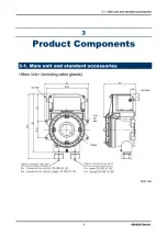
<Installation Dimensions and Maintenance Space> 


Unit: mm 

 
The following installation requirements must be met to install the detector head. 

  Attach the detector head on the wall and others using four M6 screws.   

  Tighten the hexagon socket head cap bolt fixing the lid and the main body with a tightening torque of 215.6

±

24.5N

cm. 


When closing the lid of the detector, make sure that there is no dust on screw, surfaces of the main body 
and lid. Then apply grease as specified by RIKEN KEIKI.


Lid turning jig 

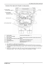
Содержание SD-D58-AC-GH

Страница 1: ...PT2E 1758 Smart Transmitter Gas Detector Head SD D58 AC GH SD D58 DC GH Operating Manual ...

Страница 2: ...tact output of the detector must be used for an external alarm lamp buzzer while the alarm signal output must be used for an indicator or external recorder If these outputs are used to control other units we shall not be responsible for any malfunctions 4 The gas sensing part of the gas detection sensor installed in this detector is made of metal porous sintered alloy permeated with an oxidation c...

Страница 3: ...1 Preparation for start up 33 5 2 Basic operating procedures 34 5 3 How to start the detector head 35 5 4 Modes 36 5 5 Maintenance mode User 37 5 6 How to exit 39 6 Operations and Functions 40 6 1 Gas alarm activation 40 6 2 Fault alarm activation 41 6 3 Low Flow Rate Abnormal Operations 41 6 4 External output operation 42 6 5 Other functions 43 7 Maintenance 44 7 1 Maintenance intervals and items...

Страница 4: ......

Страница 5: ...that performs the alarm activation when the gas concentration is over the setting value The detector head is a safety unit not an analyzer or densitometer which performs quantitative qualitative analysis measurement for gases Please fully understand the features of the detector head before using it so that it can be used properly The detector head draws air with the built in pump and detects abnor...

Страница 6: ......

Страница 7: ......

Страница 8: ......

Страница 9: ......

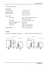
Страница 10: ...f contact and works by gas warning or trouble or both by setting ATEX Specifications Technical Data Protection Method Flameproof enclosure d Group II Category 2G Type of Protection and Marking code Ex db ⅡB H2 T4 Equipment Protection Level Gb Ambient Temperature 20 C to 53 C Electrical Data Supply voltage 24 Vdc Typ Output signal 4 to 20 mA Electrical rating DC6 5V 205mA or DC3 5V 350mA Flow rate ...

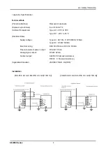
Страница 11: ... 20 C to 53 C Electrical Data Supply voltage Type AC AC100 110V 50 60Hz 120mA Type DC DC24V 360mA Electrical rating DC6 5V 205mA or DC3 5V 350mA Flow rate element power output DC2 0V 170mA Analog signal output DC24V 22mA Contact output AC250V 0 5A Load resistance DC30V 0 5A Load resistance Applicable Standard JNIOSH TR NO 43 2008 Installation SD D58 AC GH SD D58 AC GH TYPE H SD D58 DC GH SD D58 DC...

Страница 12: ...C to 53 C Electrical Data Supply voltage Type AC AC100 110V 50 60Hz 120mA Type DC DC24V 360mA Electrical rating DC6 5V 205mA or DC3 5V 350mA Flow rate element power output DC2 0V 170mA Analog signal output DC24V 22mA Contact output AC250V 0 5A Load resistance DC30V 0 5A Load resistance Applicable Standard JNIOSH TR NO 43 2008 Installation SD D58 AC GH SD D58 AC GH TYPE H SD D58 DC GH SD D58 DC GH ...

Страница 13: ......

Страница 14: ......

Страница 15: ......

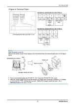
Страница 16: ...or grounding M4 6 5 Fuse Main power fuse 1 1 Only SD D58 AC GH SD D58 AC GH TYPE H 2 The power input terminal plate of SD D58 DC GH SD D58 DC GH TYPE H are as common as terminal plate for contact and transmission output See 4 5 How to wire Figure of Terminal Plate for details 3 SD D58 DC GH SD D58 DC GH TYPE H are the power input and terminal plate for contact and transmission output See 4 5 How t...

Страница 17: ......

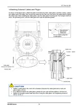
Страница 18: ...he figure above The bolt with the hexagon socket must use the stainless steel material of property class A2 70 Grease specified by RIKEN KEIKI BARRIERTA JFE 552 manufactured by NOK KLUBER If you can not prepare the specified grease use one that meets the following requirements 1 Material does not harden due to deterioration 2 Volatile solvent free 3 Material does not cause corrosion at the surface...

Страница 19: ......

Страница 20: ......

Страница 21: ......

Страница 22: ......

Страница 23: ......

Страница 24: ......

Страница 25: ...e detector head Attach the detector head on the wall and others using four M6 screws Tighten the hexagon socket head cap bolt fixing the lid and the main body with a tightening torque of 215 6 24 5N cm When closing the lid of the detector make sure that there is no dust on screw surfaces of the main body and lid Then apply grease as specified by RIKEN KEIKI Lid turning jig ...

Страница 26: ......

Страница 27: ......

Страница 28: ......

Страница 29: ......

Страница 30: ......

Страница 31: ......

Страница 32: ......

Страница 33: ......

Страница 34: ......

Страница 35: ......

Страница 36: ......

Страница 37: ... cause an electric shock or damage the detector head Connect the detector head to a grounding circuit Check that the wiring is connected to external device properly Check that the power supply voltage is compliant with the specifications Because the external contact may be activated during the adjustment take measures to prevent an activated contact from having influences on external device ...

Страница 38: ......

Страница 39: ......

Страница 40: ......

Страница 41: ......

Страница 42: ......

Страница 43: ......

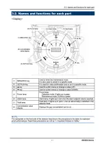
Страница 44: ...f over the detection range Over Scale is displayed on the LED Power indicator lamp POWER Green During normal operation this lights up continuously Alarm indicator lamp ALM Red It lights up when the alarm setpoint value is reached to or exceeded Contact Activation The contact is activated when the gas concentration reaches or exceeds the alarm setpoint value The contact activation is reset automati...

Страница 45: ...as detector Check that the point is free from dangers and take actions to fix the gas leak 6 2 Fault alarm activation A fault alarm is triggered when the detector head detects abnormalities After a fault alarm is triggered the fault lamp yellow lights up and an error message is displayed on the LED Determine the causes and take appropriate actions After the detector head is successfully returned f...

Страница 46: ......

Страница 47: ......

Страница 48: ...enance Power supply check Check that the power lamp lights up Concentration display check Check that the concentration display value is zero When the reading is incorrect perform the zero adjustment after ensuring that no other gases exist around it Alarm test Check the alarm circuit by using the alarm test function Span adjustment Perform the sensitivity calibration by using the calibration gas G...

Страница 49: ... or clogging Replaces a dirty or clogged dust filter Alarm test Inspects the alarm circuit by using the alarm test function Checks the alarm lamps Checks activation Checks the external alarm Checks the activation of the external alarm such as a buzzer Span adjustment Performs the span adjustment by using the calibration gas Gas alarm check Checks the gas alarm by using the calibration gas Checks t...

Страница 50: ......

Страница 51: ...lization Initializes the zero span adjustment after the sensor is replaced 2 2 Span adjustment Performs the span adjustment 2 4 Environmental setting Sets various operations and functions 2 4 0 and 2 4 3 to 2 4 F are factory set They are not typically used by the user Test mode P49 Zero adjustment P55 Span adjustment P56 Environment setting P55 2 0 Test mode Performs various tests 2 5 Various elec...

Страница 52: ... 9 are factory set They are not typically used by the user 2 7 Flow sensor setting display Displays settings of the flow sensor This is not used by the user 2 8 Enters the factory mode This is not used by the user 2 9 Returns to the user mode To 2 0 Test mode rET is displayed Press the SET key again to return to the user mode Flow sensor setting P57 ...

Страница 53: ......

Страница 54: ......

Страница 55: ......

Страница 56: ...for the RAM fault and F RO is displayed for the ROM fault For both the RAM fault and ROM fault F RA and F RO are displayed alternately 2 0 4 Press the SET key When StA is displayed press the SET key again When CAL is displayed the memory diagnosis is performed When memory is correct as a result of the diagnosis PASS is displayed Press the SET key to go back to the original state To 2 0 4 ...

Страница 57: ...lect either ON OFF and then press the SET key to confirm the selection When ON is selected in the detection mode InHI and 0 0 gas concentration value are displayed on the LED alternately As a result an alarm is not triggered to external device 2 4 2 Alarm setpoint setting Set the alarm setpoint 2 4 3 to 2 4 F They are factory set and not typically used by the user Alarm setpoint setting P53 To 2 4...

Страница 58: ......

Страница 59: ......

Страница 60: ......

Страница 61: ......

Страница 62: ......

Страница 63: ......

Страница 64: ...ed If the zero point check of the flow sensor fails it automatically returns to 2 6 3 after FAIL is displayed Install the test pump 2 6 4 Flow sensor output check Check the flow sensor output during the pump operation Flow sensor output check completed It automatically returns to 2 6 4 after PASS is displayed If the output check of the flow sensor failed it automatically returns to 2 6 4 after FAI...

Страница 65: ... AC GH SD D58 AC GH TYPE H 6 months 3 6 years 1 Flow sensor 6 months 2 years 1 Tubes 6 months 3 8 years 1 Pump unit 6 months 1 2 years 1 Chamber assembly 6 months 3 8 years 1 Sensor cap assembly 6 months 3 8 years 1 After the part is replaced the operation must be checked by a qualified service engineer For the stable operation of the detector and safety ask a qualified service engineer to take ca...

Страница 66: ......

Страница 67: ...nected short circuit Check the wiring of detector head and related devices around it Abnormal operations Disturbances by sudden surge noise etc Turn off and restart the detector head If such a symptom is observed frequently take appropriate measures to eliminate the noise Sensor abnormalities E 1 The sensor is not connected or improperly connected Check if the cable is securely fastened to the ter...

Страница 68: ...f interference gas Disturbances by interference gases such as solvents cannot be eliminated completely For information on actions such as removal filter please contact RIKEN KEIKI Disturbance by noise Turn off and restart the detector head If such a symptom is observed frequently take appropriate measures to eliminate the noise Sudden change in the environment When the environment temperature etc ...

Страница 69: ...be Gas alarm type One step alarm H Gas alarm display ALM lamp on red Gas alarm pattern Non latching Auto reset Fault alarm self diagnosis System abnormalities sensor abnormalities low flow rates Fault alarm display FAULT lamp on yellow detail display Fault alarm pattern Non latching Auto reset Alarm contact No voltage contact 1a de energized energized in response to an alarm or energized de energi...

Страница 70: ...rating humidity Below 95 RH Non condensing Structure Wall mounting type 2B 50A pipe installation supported Explosion proof structure Flame proof enclosures Explosion proof class Ⅱ 2G Ex db ⅡB H2 T4 Gb IP rating Equivalent to IP67 Dimension Approx 197 W x 292 H x 140 D mm projection portions excluded Weight Approx 5 8 kg Outer color Munsell 7 5BG5 2 Specifications subject to changes without notice ...

Страница 71: ...ge contact 1a de energized energized in response to an alarm or energized de energized in response to an alarm Contact capacity 250 VAC 0 5 A 30 VDC 0 5 A resistant load Transmission system Three wire analog transmission in common with power supply power supply signal common HART communication Transmission specifications 4 20 mA DC no insulation load resistance under 300 Ω HART7 HART communication...

Страница 72: ...m display FAULT lamp on yellow detail display Fault alarm pattern Non latching Auto reset Alarm contact No voltage contact 1a de energized energized in response to an alarm or energized de energized in response to an alarm Contact capacity 250 VAC 0 5 A 30 VDC 0 5 A resistant load Transmission system Analog transmission Transmission specifications 4 20 mA DC no insulation load resistance under 300...

Страница 73: ...sponse to an alarm or energized de energized in response to an alarm Contact capacity 250 VAC 0 5 A 30 VDC 0 5 A resistant load Transmission system Analog transmission HART communication Transmission specifications 4 20 mA DC no insulation load resistance under 300 Ω HART7 HART communication Transmission cable Shielded cable of CVVS etc 1 25mm2 or 2 0mm2 2 core when the contact is not used Shielde...

Страница 74: ...et Alarm contact No voltage contact 1a de energized energized in response to an alarm or energized de energized in response to an alarm Contact capacity 250 VAC 0 5 A 30 VDC 0 5 A resistant load Transmission system three wire type analog transmission common cable for power and signal power signal common Transmission specifications 4 20 mA DC no insulation load resistance under 300 Ω Transmission c...

Страница 75: ...voltage contact 1a de energized energized in response to an alarm or energized de energized in response to an alarm Contact capacity 250 VAC 0 5 A 30 VDC 0 5 A resistant load Transmission system Three wire type analog transmission common cable for power and signal power signal common HART communication Transmission specifications 4 20 mA DC no insulation load resistance under 300 Ω HART7 HART comm...

Страница 76: ... energized in response to an alarm or energized de energized in response to an alarm Contact capacity 250 VAC 0 5 A 30 VDC 0 5 A resistant load Transmission system Analog transmission Transmission specifications 4 20 mA DC no insulation load resistance under 300 Ω Transmission cable Shielded cable of CVVS etc 1 25mm2 or 2 0mm2 2 core when the contact is not used Shielded cable of CVVS etc 1 25mm2 ...

Страница 77: ...in response to an alarm or energized de energized in response to an alarm Contact capacity 250 VAC 0 5 A 30 VDC 0 5 A resistant load Transmission system Analog transmission HART communication Transmission specifications 4 20mADC no insulation load resistance under 300Ω HART7 HART communication Transmission cable Shielded cable of CVVS etc 1 25mm2 or 2 0mm2 2 core when the contact is not used Shiel...

Страница 78: ...larm contact No voltage contact 1a de energized energized in response to an alarm or energized de energized in response to an alarm Contact capacity 250 VAC 0 5 A 30 VDC 0 5 A resistant load Transmission system three wire type analog transmission common cable for power and signal power signal common Transmission specifications 4 20 mA DC no insulation load resistance under 300 Ω Power contact tran...

Страница 79: ...arm contact No voltage contact 1a de energized energized in response to an alarm or energized de energized in response to an alarm Contact capacity 250 VAC 0 5 A 30 VDC 0 5 A resistant load Transmission system Three wire type analog transmission common cable for power and signal power signal common Transmission specifications 4 20mADC no insulation load resistance under 300Ω HART7 HART communicati...

Страница 80: ......

Страница 81: ...centration unit that means part per million of the combustible gas to be detected Calibration Adjusts the readings to the calibration gas concentration value by using the calibration gas Zero suppression A function to cut off the specific drifting that the sensor has Alarm delay time A function which temporarily suspends activation to prevent a false alarm caused by noise from its outside INHIBIT ...

Страница 82: ......

Отзывы: