background image

RIGOL


RP1003C/1004C/1005C/1006C User Guide 

NOTE


For RP1003C/RP1004C, if zero adjustment is not possible in Step 6, turn the 

coarse adjustment trimmer to bring the trace within the range of adjustment by 

the zero adjustment dial. While turning the coarse adjustment trimmer, do not 

subject it to a thrust. Doing so may cause the trimmer to come off. To turn the 

trimmer, use a screwdriver with the following flat blade made of non-conductive 

materials such as ceramic: 0.4 mm in thickness, 1.8 mm in width, and 10 mm in 

length or longer

.


Measurement Procedure 


1.


Check that the system is safe, and that the preparations described in the 

preceding section have been carried out. 


2.


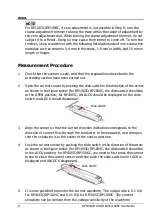
Open the current sensor by pushing the slide switch in the direction of the arrow 

as shown in the figure below (for RP1003C/RP1004C, the slide switch should be 

at the OPEN position; for RP1005C, UNLOCK should be displayed on the slide 

switch and LOCK should disappear). 


3.


Align the sensor so that the current direction indication corresponds to the 

direction of current flow through the conductor to be measured, and clamp so 

that the conductor is in the center of the sensor aperture. 


4.


Lock the current sensor by pushing the slide switch in the direction of the arrow 

as shown in the figure below (for RP1003C/RP1004C, the slide switch should be 

in the LOCK position; for RP1005C/RP1006C, you need to first press the current 

probe to close the current sensor and then push the slide switch until LOCK is 

displayed and UNLOCK disappears). 


5.


It is now possible to monitor the current waveform. The output rate is 0.1 V/A 

for RP1003C/RP1004C and 0.01 V/A for RP1005C/RP1006C. The current 

sensitivity can be derived from the voltage sensitivity of the waveform 

Slide Switch 

Slide Switch 

Содержание RP1003C

Страница 1: ...User Guide RP1003C 1004C 1005C 1006C Current Probe Sept 2020 RIGOL TECHNOLOGIES CO LTD ...

Страница 2: ......

Страница 3: ...lication is subject to change without notice RIGOL shall not be liable for either incidental or consequential losses in connection with the furnishing use or performance of this manual as well as any information contained Any part of this document is forbidden to be copied photocopied or rearranged without prior written approval of RIGOL Product Certification RIGOL guarantees that this product con...

Страница 4: ...sing the relevant function In the manual the symbol indicates particularly important information that the user should read before using the device The symbol printed on the device indicates that only insulated conductors suited to the voltage of the circuit under test can be measured The following symbols in this manual indicate the importance of cautions and warnings DANGER Indicates that incorre...

Страница 5: ... 2 RP1005C RP1006C Parts Overview 3 Parts Introductions 4 To Use the Current Probe 6 Preparations for Measurement 6 Demagnetizing and Zero Adjustment 6 Measurement Procedure 8 Precautions for Measurement 10 Specifications 14 RP1003C RP1004C 14 RP1005C 15 RP1006C 16 Appendix 18 Appendix 1 Amplitude frequency Characteristics 18 Appendix 2 Relation between Max Input Current and Frequency 20 Appendix ...

Страница 6: ...rface while taking measurements 4 Before clamping the conductor being measured make sure that the insulation on the conductor is undamaged Also take care not to damage the insulation when clamping the conductor Any damage to the insulation could cause an electric shock 5 The probe is made for use with the RP1000P power adapter 6 To prevent fire avoid damage or burns of the measurement object devic...

Страница 7: ...the current probe RP1003C RP1004C RP1005C RP1006C WARNING 1 Do not allow the device to get wet and do not take measurements with wet hands This may cause an electric shock 2 Do not press the demagnetizing switch DEMAG to perform demagnetization while the conductor being measured is clamped Doing so could damage the circuitry or cause an accident that might result in injury or death 3 Ensure that t...

Страница 8: ... in handling it 6 The mating surfaces of the sensor head are precision ground and should be treated with care If these surfaces are scratched performance may be impaired 7 Measurements are degraded by dirt on the mating surfaces of the sensor head so keep the surfaces clean by gently wiping with a soft cloth 8 Foreign substances such as dust on the mating surfaces of the sensor head can cause acou...

Страница 9: ...e impossible in the presence of strong magnetic fields such as near transformers and high current conductors or in the presence of strong electromagnetic fields such as near radio transmitters Service When sending the probe for repair pack carefully to prevent damage during transportation Keep the cushioning materials within the package to avoid the probe to be damaged Be sure to include details o...

Страница 10: ......

Страница 11: ...n easily capture the current waveforms Main Features Highly accurate current detection Easy current measurement Broadband frequency characteristics RP1003C DC to 50 MHz RP1004C DC to 100 MHz RP1005C DC to 10 MHz RP1006C DC to 2 MHz RP1003C RP1004C Compact design permits measurement of low current levels RP1005C RP1006C Large diameter allows high current measurements Easy protect function at excess...

Страница 12: ... RP1004C Parts Overview Figure 1 RP1003C RP1004C Parts For the parts from 1 to 7 noted in the above figure please refer to Parts Introductions Current Direction Indication UNLOCK Indication Terminator Power Supply Cable Sensor Cable 5 2 7 4 3 1 6 Sensor ...

Страница 13: ... Parts Overview Figure 2 RP1005C RP1006C Parts For the parts from 1 to 7 noted in the above figure please refer to Parts Introductions Current Direction Indication LOCK Indication Terminator Power Supply Cable Sensor Cable 1 7 4 3 1 6 Sensor UNLOCK Indication 2 ...

Страница 14: ...itch the UNLOCK indication disappears 2 Sensor head This clamps the conductor being measured and carries out the actual current measurement It is a precision assembly that contains a molded component a ferrite core and a Hall effect element It may be damaged if subjected to sudden changes at ambient temperature or mechanical strain or shock and therefore great care should be exercised in handling ...

Страница 15: ...06C the probe must be used with a waveform measurement instrument that has an input impedance of at least 1 MΩ Accurate measurement is not possible with the waveform measurement instrument whose input impedance is 50 Ω If using BNC banana plug adapters or similar to connect to input terminals other than BNC connectors make sure the polarity is correct Turn the collar until it clicks and check that...

Страница 16: ...e power plug of the current probe to the power receptacle of the RP1000P 4 Turn the RP1000P power switch on and check that the front panel power indicator lights on 5 Wait at least 30 minutes after turning on the current probe Immediately after power is supplied offset drift may increase due to the effects of self heating of the device and other factors To ensure accurate measurement wait at least...

Страница 17: ...e current probe is clamping a conductor to be measured Demagnetizing causes current to flow into the conductor which may damage parts in the circuit to be measured RP1003C RP1004C RP1005C RP1006C Check that the conductor being measured is not clamped when supplying power to the current probe for the same reason Demagnetized waveforms are generated when supplying electric power 4 Make sure the curr...

Страница 18: ...gure below for RP1003C RP1004C the slide switch should be at the OPEN position for RP1005C UNLOCK should be displayed on the slide switch and LOCK should disappear 3 Align the sensor so that the current direction indication corresponds to the direction of current flow through the conductor to be measured and clamp so that the conductor is in the center of the sensor aperture 4 Lock the current sen...

Страница 19: ...e used simultaneously with the RP1000P depending on the current to be measured The current consumption of the current probe depends on the current to be measured Make sure that the total current consumption of the current probes does not exceed the rated output current of the power supply when multiple current probes are connected to the same power supply The figure below is the relation curve bet...

Страница 20: ...ous input range is based on the heat that is internally generated during the measurement Never input current in excess of this level Exceeding the rated level may result in damage to the probe 2 The device may sustain damage from self heating even at current levels that are lower than the maximum current value defined by the maximum rated current The maximum rated current is a recommended value th...

Страница 21: ...n if the input current does not exceed the rated continuous input range continuous input for an extended period of time may result in activation of the safety circuit to prevent damage resulting from heating of the sensor 6 At high ambient temperature the built in safety circuit may activate at current input levels below the rated continuous input range 7 Continuous input of current exceeding the ...

Страница 22: ...d This sound may also occur during demagnetizing operation but it does not represent a malfunction device failure 5 If foreign matter becomes adhered to the mating surfaces on the sensor head so that a slight gap exists between the upper and lower sensors the sensor head may emit a resonant sound Any foreign matter should be removed using the cleaning method described in this manual 6 An increase ...

Страница 23: ...o strong external magnetic fields such as transformers and high current conductors or in locations subject to strong external electric fields such as radio transmission equipment 11 At high frequencies common mode noise may affect measurements taken on the high voltage side of circuits If this occurs reduce the frequency range of the waveform measuring instrument or clamp onto the low voltage side...

Страница 24: ...tween Max Input Current and Frequency RP1003C RP1004C Maximum Peak Current Value Non continuous 50 A peak Gain 0 1 V A Amplitude Accuracy 1 0 rdg 1 mV 30 Arms 2 0 rdg 50 A peak DC 45 Hz to 66 Hz input within continuous maximum input range Noise 2 5 mArms for BW 20 MHz waveform measuring instrument Input Impedance Refer to Appendix 3 Input Impedance Typical RP1003C RP1004C Temperature Coefficient f...

Страница 25: ...sions Terminator approx 27H 55W 18D mm Mass RP1003C approx 230g RP1004C approx 240g Accessories User Guide Probe Case Safety EN61010 EMC EN61326 RP1005C Bandwidth DC to 10 MHz 3 dB refer to Appendix 1 Amplitude frequency Characteristics RP1005C Rise Time 35 ns Maximum Continuous Input Range 150 Arms refer to Appendix 2 Relation between Max Input Current and Frequency RP1005C Maximum Peak Current V...

Страница 26: ...osing up to 10 000 times Effect of External Magnetic Fields 150 mA in a DC or 60 Hz 400 A m magnetic field Diameter of Measurable Conductor 20 mm Measurable Conductor Insulated conductor Cable Length Sensor cable approx 2 m Power supply cable approx 1 m External Dimension Sensor approx 176W X 69H X 27D mm Terminator approx 27H X 55W X 18D mm Mass Approx 500g Accessories User Guide Probe Case Safet...

Страница 27: ...ly Voltage 12 V 0 5 V Operating Temperature and Humidity Range 0 C to 40 C 80 RH no condensation Storage Temperature and Humidity Range 10 C to 50 C 80 RH no condensation Location for Use Indoor altitude up to 2 000 m Pollution Degree 2 Period of Guaranteed Accuracy 1 year opening closing up to 10 000 times Effect of External Magnetic Fields 800 mA in a DC or 60 Hz 400 A m magnetic field Diameter ...

Страница 28: ...RIGOL 18 RP1003C 1004C 1005C 1006C User Guide Appendix Appendix 1 Amplitude frequency Characteristics RP1003C RP1004C ...

Страница 29: ...RIGOL RP1003C 1004C 1005C 1006C User Guide 19 RP1005C RP1006C ...

Страница 30: ...RIGOL 20 RP1003C 1004C 1005C 1006C User Guide Appendix 2 Relation between Max Input Current and Frequency RP1003C RP1004C ...

Страница 31: ...RIGOL RP1003C 1004C 1005C 1006C User Guide 21 RP1005C RP1006C ...

Страница 32: ...RIGOL 22 RP1003C 1004C 1005C 1006C User Guide Appendix 3 Input Impedance Typical RP1003C RP1004C ...

Страница 33: ...RIGOL RP1003C 1004C 1005C 1006C User Guide 23 RP1005C RP1006C ...

Отзывы: