


16 |
P a g e
R i g e l M e d i c a l U n i - T h e r m u s e r M a n u a l V 1 . 0
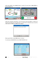
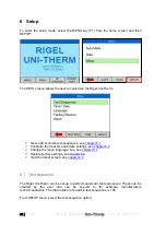
Press SHOW DIAGRAM to obtain help on the connection between the Uni-Therm and
the EUT.
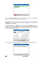
Press START to confirm the settings and start the test.
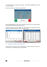
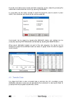
During the Graph power test, the Rigel Uni-Therm will display the power distribution
graph.
At the end of the test, toggle between GRAPH MODE and DATA by pressing the GOTO
DATA fast key
In the automatic mode, a reference graph can be included in the test to automatically
detect of the current graph meets the criteria of the reference graph. A full description of
how to create a power reference graph is provided in Appendix D.
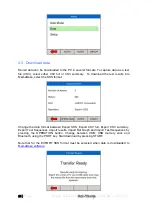
2.3.3 External Load mode
The external load mode allows the user to monitor the power characteristics under a
specific load condition, utilising external loads or under short circuit condition i.e. for
calibration purpose. During the test, the EUT is connected to the external loads and then
to the measuring device of the Uni-Therm (MD). The Uni-Therm will calculate the power
characteristics at the set external load by measuring the HF current through the MD.
The maximum current measurement during this test is limited to 8A rms.


