background image

26


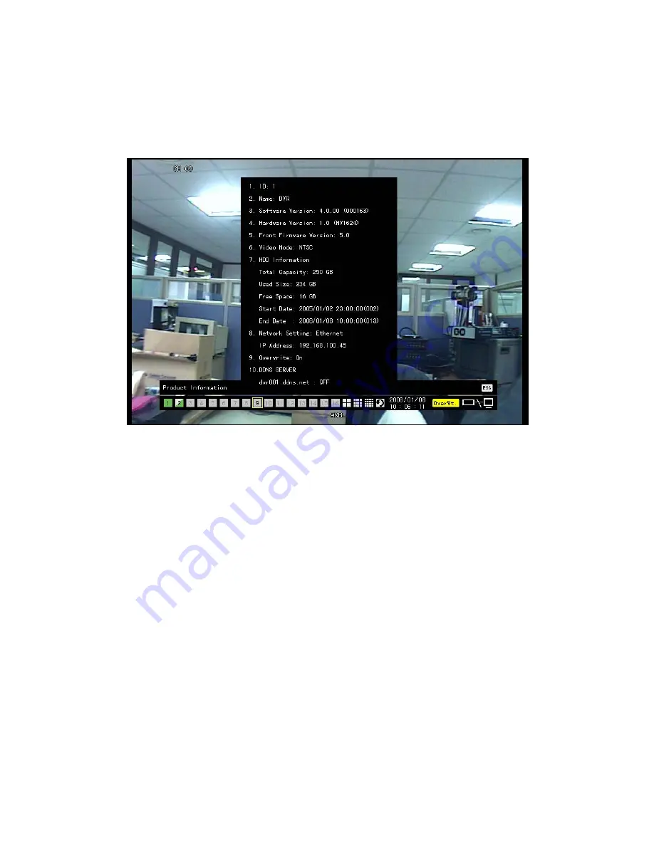
4-5-1  System Information 


  On the real-time monitoring screen, select {

Live Menu} 

Æ

 {Status}

 Product mode information will then be displayed as shown in Figure 4-4. 


[Figure 4-4. Product Information Window] 


 The product ID shall be unique (1~99, 255). Only when the product ID and the remote 

controller ID match can the DVR system be remotely controlled. 
 

4-5-2  Channel Grouping 


 On the real-time monitoring screen, select 

{Live Menu} 

Æ

 {Channel Grouping}

 The user can select the screen split mode by selecting 

{Menu} 

Æ

 {Display Setting}

 On the monitoring screen, go to the channel selection window and select the channel to 

be changed by group.  

 On the selection window, select a channel using the arrow keys and the Select button. 


 Group Setup is not supported for the 1

-split mode. 

 The user can change the channel location in the group using the mouse.


 Changing the screen split mode causes other split modes to be changed as well.


Содержание MV-1624

Страница 1: ...Version 1 8 MV Series USER S GUIDE RIFATRON ...

Страница 2: ......

Страница 3: ...e using the product 1 To prevent electric shock when installing moving or opening the DVR and peripheral devices connect and disconnect the cables as instructed All cables must be connected to grounded power outlets 2 If the product is installed near a power outlet make sure it can be unplugged easily 3 Do not use the DVR in water or in wet places 4 Keep the vinyl packing materials used for the DV...

Страница 4: ...ing internally even after the switch is turned OFF 6 Do not place a heavy object on top of the product 7 Do not drop a conductive object in the ventilation holes 8 Allot sufficient space for system cabling 9 Use only the parts indicated in the manual Do not disassemble repair or modify the product without permission 10 Incorrect system setup may cause malfunction 11 Shut down the system normally a...

Страница 5: ... Starting and Exiting the System 21 4 1 1 Starting the System 21 4 1 2 Exiting the System 21 4 2 Monitoring 21 4 2 1 Screen Division and Automatic Screen Conversion 21 4 2 2 Menus in Monitoring Mode 22 4 2 3 Moving the recording status window 23 4 3 System Login 23 4 3 1 User Account 23 4 3 2 Login 24 4 3 3 Logout 24 4 4 Audio Recording and Playback 25 4 4 1 Setting up the Audio Recording 25 4 4 2...

Страница 6: ...ecording 38 4 10 1 Recording Types 38 4 10 2 Recording Setup 38 4 10 3 Viewing the Recording Status 38 4 10 4 Starting and Stopping Record All 39 4 11 Search 40 4 11 1 Selecting the Search Mode 40 4 11 2 Selecting the Search Method 40 4 11 3 Search using the file list 40 4 11 4 Multi Channel Search 41 4 11 5 Multi Time Search 41 4 11 6 Multi Day Search 42 4 12 Backup 43 4 12 1 Backup in Real time ...

Страница 7: ...stem 63 5 1 8 Storage 70 5 1 9 NTP 76 5 1 10 Advanced 82 5 2 Additional Setup 84 5 2 1 Selecting the Additional Setup Menu 84 5 2 2 PTZ setup 84 5 2 3 Network setup 86 A P P E N D I X 90 1 PTZ Camera Protocol 90 2 Recommended HDD 90 3 Recommended USB2 0 Device 90 4 Memory Stick 91 5 2 5 Potable USB HDD 91 6 CD RW DVD RW 91 7 IEEE1394 Exterial Storage 91 8 DAT Interior Exterior 91 ...

Страница 8: ...6 ...

Страница 9: ...es and displays them as clean quality images For users convenience front touch pad remote controller and mouse are provided Powerful network functions including remote monitoring and remote system setup modification are also supported The maximum recording frame rate for MV Series is 480fps 240fps 1 2 Major Features z Stable Standalone DVR Embedded Linux z Video output Monitor Output 1 BNC 1 VGA L...

Страница 10: ...Auto Continuous Event sensor motion sound recording z Scheduled recording feature z Multi language support Automatic emailing z PTZ control through RS485 communication z Remote monitoring software Remote monitoring through the web browser PDA z Storage device Internal storage device Max of 2HDD Max of 1TB External storage device IEEE1394 RAID external storage device ...

Страница 11: ...omponents After unpacking the product check whether the following accessories are included Remote Controller CMS CD Remote Monitoring Software Two AAA 1 5V batteries Power Cord User Manual Rack Mounting Handle ...

Страница 12: ...d in Playback mode Relay Control in Monitoring mode 7 Reverse Frame by Frame or TAB STATUS Backward Playback Frame by Frame in Playback mode View System Configuration Change Display Configuration in Monitoring mode 8 PAUSE LOCK Pause in Playback mode Lock in Monitoring mode 9 Forward Frame by Frame or TAB LOG Playback Frame by Frame in Playback mode View System Log in Monitoring mode 10 Forward Pl...

Страница 13: ...an defect or recording interruption 22 POWER LED Power On Off 23 SELECT Selects the category or executes automatic screen conversion 23 MOVE DISPLAY Moves from one category to another or changes the display mode 24 IR Sensor Remote controller input part 25 USB Port Connection port to the USB mouse and USB memory stick 26 POWER Button Turn the system power ON or OFF ...

Страница 14: ...C BNC 5 AUDIO IN Audio input connection RCA 6 NTSC PAL VGA TV Used to select the video input format Used to select the video output format DA 2 7 iEEE1394 External backup device connection 1394 Port 8 Ethernet ADSL cable modem and Ethernet 10 100 Base T connection RJ 45 9 RS 232C Serial cable connection for system upgrades checking D SUB 9P 10 VGA Connection for the VGA monitor D SUB 15P 11 TV Con...

Страница 15: ...13 z 8ch Back Part MV 824 z 4ch Back Part MV 424 ...

Страница 16: ... Terminal 1 CCTV camera Video input 2 CCTV monitor or PC monitor TV or VGA 3 Mouse USB 1 The input video type must be either NTSC or PAL these two types must not be used together 2 Select the input video format NTSC PAL using the Config switch on the rear side of the product 3 Select the output monitor type VGA TV using the Config switch on the rear side of the product ...

Страница 17: ...85 wire to the terminal block on the rear side of the DVR Connect TRX and TRX 2 SPOT Monitor The Spot monitor is a CCTV monitor that displays events SPOT The Spot monitoring function displays video from the channel detecting an event motion sensor or sound in full screen Events are checked every second If events are detected from multiple channels the video from the channel with the latest event i...

Страница 18: ... Normal Open NO Normally open closes when a signal is received 2 Relay Connection Outputs alarm signals to external devices such as LED and siren by relaying them to these external devices Connect the external alarm device to the COM or Out port of the sensor relay terminal block Relay types include Normal Close NC and Normal Open NO For more information on setup by sensor type refer to Data Setup...

Страница 19: ...hannels 1 0 NUMBER Enables input of numeric data ID Sets up the remote controller ID B System operation and setup buttons MENU Data Schedule System Set up ESC Exits the current menu or selects the upper menu SEARC H Searches recorded images SELECT Selects the category or executes automatic screen conversion COPY Copy Recorded Video PTZ Shifts to PTZ camera control mode MOVE Moves from one category...

Страница 20: ... Play Fast Reverse Reverse play Rewind D Buttons for other features Monitoring mode PLAY Plays the recorded images LOG Enables viewing the system log list LOCK Locking the system STATUS Views system information and changes the display setup RELAY View Relay Status and Manual Operation Setting up the remote controller ID Example When the remote controller ID is set to 1 ...

Страница 21: ...19 Press the ID button enter a two digit remote controller ID and press the ID button again To control all DVRs with different IDs set the remote controller ID to 999 ...

Страница 22: ...20 3 2 Mouse The USB mouse can be used to operate the system ...

Страница 23: ...ller On the password input screen enter a new password using the numeric buttons and the arrow keys After authentication is completed the alarm will sound for 20 seconds and the system will be terminated 4 2 Monitoring After the system is booted images will be displayed on a screen divided into 16 sub screens in the case of 16 channel DVR The screen can be divided into 1 4 9 and 16 sub screens Aut...

Страница 24: ...nge mode by selecting the Select Automatic Change button in 1 4 9 Sub Screen mode Click the Select button again to return to the previous mode Using the Up Down button the user can select the change interval from 1 second to 5 seconds to set the change interval however multiple cameras should be connected The user can also set the change interval by right clicking any part of the screen 4 2 2 Menu...

Страница 25: ...window will then be bordered At this time drag the recording status window The user can move the recording status window using only the mouse 4 3 System Login 4 3 1 User Account System users are divided into local administrators and general users The local system administrator can use all functions Local admin The local administrator can use all functions System Power On Off Setup Monitoring and P...

Страница 26: ...Playback Copy and Camera TV Setup functions the user should log in first for security purposes Figure 4 2 Login Window On the real time monitoring window select Live Menu Æ Login The login window will then appear as shown in Figure 4 2 Enter the password 4 3 3 Logout After logging out the user cannot use functions such as Main Setup App Setup Search Playback Copy and Camera TV Setup functions On t...

Страница 27: ... in Figure 5 1 Select Recording Setup Æ Recording Æ Audio using the arrow keys and the Select button Set up the audio 4 4 2 Audio Live On the real time monitoring screen select Live Menu Æ Control Æ Audio Select the audio channel 4 5 Viewing System Information and Changing the Display Setup Basic system information is displayed as shown in Figure 4 3 Figure 4 3 Recording Status Window ...

Страница 28: ...nnel Grouping On the real time monitoring screen select Live Menu Æ Channel Grouping The user can select the screen split mode by selecting Menu Æ Display Setting On the monitoring screen go to the channel selection window and select the channel to be changed by group On the selection window select a channel using the arrow keys and the Select button Group Setup is not supported for the 1 split mo...

Страница 29: ... To adjust the Hue select a channel on the screen Control the hue of the selected channel using the arrow keys Activate the channel selection window using the ESC button and adjust the hue of the other channels by repeating steps 3 and 4 4 5 6 Adjusting Saturation On the real time monitoring screen select Live Menu Camera TV Setting Saturation To adjust the saturation select a channel on the scree...

Страница 30: ... the screen The level at which such condition does not occur is the proper control range for the monitor 4 5 10 Display Hide Camera Name On the real time monitoring screen select Live Menu Æ Display Setting Æ Name Camera Name Select the On Off status using the arrow keys and the Select button 4 5 11 Adjusting the Screen Border On the real time monitoring screen select Live Menu Display Setting Bor...

Страница 31: ...back 4 8 1 Shifting to Playback Mode On the real time monitoring screen select Live Menu Æ Playback to shift to Playback mode The contents will then be played back from the point when playback was last stopped 4 8 2 Playback Menu In Playback mode the user can control all functions using Playback Menu Figure 4 5 Playback Menu Select or right click the Menu button The Playback menu will then appear ...

Страница 32: ...execute smart search by selecting a channel using the arrow keys and the Select button 4 8 4 Multi Time The user can play back the video contents of a certain channel recorded at different times The video contents can be sorted by time in ascending or descending order ...

Страница 33: ...31 Time Figure 4 6 Multi Time Playback ...

Страница 34: ...ntents can be sorted by date in ascending or descending order Figure 4 7 Multi Day Playback Screen In Playback mode select Playback Menu Æ Multi Day The user can execute multi day playback by selecting a certain channel using the arrow keys and the Select button 4 8 6 Multi Channel The user can play back the video contents at multiple times as recorded in a certain time zone In Playback mode multi...

Страница 35: ...hannel Playback mode both backward playback and forward playback are possible Using the Up Down button the user can adjust the playback speed between ⅹ1 29 and ⅹ29 and fast forward or rewind at a speed between x30 and x300 Description of the Search Buttons Button Name Features Forward playback Fast forward Playback forward ⅹ1 Fast forward ⅹ30 Forward Frame by Frame Frame by frame playback Pause Pa...

Страница 36: ...corded data In Playback mode select Playback Menu Æ Event Select an event using the arrow keys and the Select button 4 8 11 Go To The Date Time The user can play back the data recorded at a specified time on a specified date In Playback mode select Playback Menu Æ Go To The Date Time On the time setting window set the folder count time and channel using the arrow keys and the Select button After c...

Страница 37: ...electing Playback Menu Go To The First in Playback mode 4 8 13 Go To The Last The user can search and play back the last recorded data The latest data can be played back by selecting Playback Menu Go To The Last in Playback mode The user can use the Go To The First and the Go To The Last functions only in Multi Channel mode ...

Страница 38: ...file copy backup failure setup start end playback and other basic system operations Recording Event Logs related to recording e g motion detection sensor detection and sound detection Network Logs related to network operations e g network login network logout and network live Fail Logs related to system operation failures e g signal loss and network connection failure All Logs related to all syste...

Страница 39: ...o check the logs by time and type on each page The user can shift to Playback mode in a certain time zone for the log list by selecting the Playback button playback will start from the time point when logs are saved Viewing Time Change related Log Data The stored data folder is updated each time the user changes the time A blue triangular icon is displayed on the date each time a change is made in...

Страница 40: ...n external sensor is generated recording will be done based on the event frame value Sound When sound is detected recording will be made based on the event frame value 4 10 2 Recording Setup The user can set the recording type by selecting Main Setup Æ Data Setup For more information see Main Setup Æ Data Setup Æ Recording Setup 4 10 3 Viewing the Recording Status The user can view the recording s...

Страница 41: ...e monitoring mode select Live Menu Æ Recording Enter the password of the local system administrator On the recording stop confirmation window select the Yes button Any channel recording in progress will then stop and the corresponding status will be displayed on the recording status window 2 Starting Record All In real time monitoring mode select Live Menu Æ Recording On the login window enter the...

Страница 42: ...ne of these two methods can be used 4 11 3 Search using the file list Select the desired search date The one hour file list for the recorded video will then be displayed Select the desired file using the arrow keys Viewing the List of Files with Changed Time 1 Whenever a user changes the time by selecting Main Setup Æ NTP Æ Date and Time a new folder directory is created and the files recorded in ...

Страница 43: ...blue Indicates that recording was done before the time was changed Move the time line to a specific time point using the arrow keys or the numeric buttons and press the Search button Selecting the time causes the recorded video for each channel to be displayed as a bar graph in minute units Move the time line to a certain time point using the arrow keys and the numeric buttons and press the Select...

Страница 44: ...Day Search The user can play back the video contents of a certain channel recorded on different dates Video contents of other dates can be searched in Multi Day Search mode The user can search video contents by date as in the Multi Channel Search mode Select the desired date The date list time and channel will then be sorted in descending order Select the desired time and channel using the arrow k...

Страница 45: ...emaining backup procedures see Backup Common Backup Procedure Data obtained before the time was changed cannot be backed up 4 12 2 Backup in Search Mode Select Search Multi Channel Minute Select Menu Copy Backup The automatic backup start time is set to the year month date hour minute set in search mode and the end time to the last minute second of the data existing at the selected time All channe...

Страница 46: ...e time of backup are backed up automatically Depending on the divided screen mode however only those channels that can be viewed may be selected For the remaining backup procedures see Backup Common Backup Procedure 4 12 5 Common Backup Process Figure 4 12 Backup Window Figure 4 12 shows the initial backup window menus A list of devices that can be selected as well as simple information on the cur...

Страница 47: ... time displayed at this time means that there is data at the corresponding time If there is no data however the time is not included in the Scroll Box Changing the backup time causes the name of the directory to be backed up to be changed as well To select the backup time channel or media select Menu Æ Channel Menu Æ Time or Menu Æ Media The channel to be backed up can only be selected if there is...

Страница 48: ...selected device is an ODD device a prompt asking whether to back up the ODD device will be displayed 4 14 Print In real time monitoring playback or log mode the user can print the currently displayed image using the Print function To print the displayed image select Live Menu Æ Copy Æ Print in real time monitoring mode or Playback Menu Copy Print in Playback or Log mode The Print function can be u...

Страница 49: ...he channel screen border is highlighted in blue 4 15 3 PTZ Control 1 Horizontal Vertical rotation Select a PTZ camera using the arrow keys and the Select button The PTZ control window will then appear Move horizontally or vertically using the arrow keys To shift to screen split mode select Menu Display Setting and screen split mode 2 Zoom in Zoom out To shift to Zoom In Out mode press the PTZ butt...

Страница 50: ...ing is completed the set numbers are displayed in blue and the PTZ setting status with the set number will be stored 5 Using the Preset Function In Vertical Horizontal PTZ rotation Zoom In Out and Focus Control modes use the numeric buttons 6 Using the Tour feature For more information on setting the Tour feature select Additional Setup PTZ Setup Tour After the Tour is set No 9 or No 0 will be dis...

Страница 51: ...other major features 5 1 1 Starting the Main Setup On the real time monitoring screen select Live Menu Æ Main Setup The Main Setup window will then appear as shown in Figure 5 1 5 1 2 Data Selection Data 1 Data 4 On the Main Setup window select data using the arrow keys up to four data types are supported ...

Страница 52: ...nu Convert Two modes will be available 1 Data Mode This is a method of setting up the data for Channel Nos 1 16 based on the data profile of Data 1 Data 4 as shown in Figure 5 1 Figure 5 1 Main Setup Window Data Mode 2 Channel Mode This is a method of setting up the data for Channel Nos 1 16 based on four channel groups as shown in Figure 5 2 ...

Страница 53: ...a select Save As On the selection window select the desired data using the arrow keys and the Select button Exiting without saving the changes causes a prompt asking whether to save the new setting or not to be displayed Select Yes to save the changes To apply the new setting the user should save the new setting 5 1 5 Recording Setup 1 Camera Channel 1 Title Used to name each camera channel ...

Страница 54: ...hannel using the arrow keys and the Select button On the selection window select the third row and decide whether to connect or disconnect the camera channel When the camera channel is set to disconnected the video contents will not be displayed even if the camera is actually connected 2 Recording Used to set the resolution recording quality recording type recording frame and audio recording statu...

Страница 55: ... selecting the recording mode based on each setup value Continuous Continuous recording is done based on the normal frame value Motion Recording is done based on the event frame setting in case motion is detected Sensor If input signal is generated from an external sensor recording is done based on the event frame setting Sound When sound is detected recording will be done based on the event frame...

Страница 56: ...s Select Recording Rate for the channel using the arrow keys and the Select button On the selection window select the frame rate In adjusting the frame rate setting the frame rate to be higher than the maximum frame rate causes a menu to be displayed as shown in Figure 5 3 The yellow colored channel is currently being set as shown in Figure 5 3 Any unused channel will be deleted first Figure 5 3 F...

Страница 57: ...oti for the channel using the arrow keys and the Select button On the selection window select All Partial Motion is detected in the user defined areas of an image only Select Event Æ Moti for the channel using the arrow keys and the Select button On the selection window select Partial The grid will then be displayed on the screen Select the area where motions will be detected using the arrow keys ...

Страница 58: ...nsor is detected the video of the corresponding channel will be recorded Select Event Sens for the channel using the arrow keys and the Select button On the selection window select an external sensor channel using the arrow keys and the Select button Select Event Sens Sensor Type for the channel using the arrow keys and the Menu button On the selection window select the sensor type using the arrow...

Страница 59: ...ter the occurrence of an event Select Event Æ Post for the channel using the arrow keys and the Select button On the selection window select the time value using the arrow keys and the Select button Time is set in seconds Whenever an event is detected recording will be done for the set time To set all channels to the same value at the same time go to the top of the Post column and press the SELECT...

Страница 60: ...rms through the buzzer mail spot monitor or relay in case of an event 1 Buzzer This feature is used to run the buzzer in the product in case of an event Select Alarm Out Buz for the channel using the arrow keys and the Select button On the selection window select the event subject to buzzer operation e g movement sensor sound using the arrow keys and the Select button and decide whether to activat...

Страница 61: ... to cancel Figure 5 4 Preset Action Setting Window To set all channels to the same value at the same time go to the top of the Preset column and press the Select button Preset can be set to 1 8 3 Email When an alarm or an event occurs emails will be sent to the specified email address Select Alarm Out Æ Mail for the channel using the arrow keys and the Select button On the selection window select ...

Страница 62: ...he arrow keys and the Select button On the selection window select the event type and decide whether to use the Relay function or not using the arrow keys and the Select button Select Alarm Out Relay Relay Type for the channel using the arrow keys and the Menu button On the selection window select the relay type using the arrow keys and the Select button To set all channels at the same time go to ...

Страница 63: ...elected date and time to be set b Select or right click the Menu button to make the setting for all time zones after the selected date and the time zone On the selection window set the data using the arrow keys and the Select button 2 Set each column Go to the top of the time column using the arrow keys Select the data you want to set a Press or double click the Select button to set only one colum...

Страница 64: ... Page shows the page count when there are more than 15 holidays Current page Total page Holiday No denotes the holiday number arranged by date Number of selected holidays Total number of holidays Date shows the date of the holiday Click the Recording Schedule menu and select Menu Æ Holiday On the Holiday Registration window select the date using the arrow button and the Select button and press the...

Страница 65: ...r ID Used to name the remote controller for running the system 5 Time Display Type Used to set the date display format 6 User Registration Used to register add or delete users 7 Buzzer Used to turn the System Buzzer ON OFF 8 Set Alarm Time Used to set the alarm generation time in seconds 9 Upgrade Upgrades the system firmware 10 Reset Used to execute reset 11 PTZ Home Position Time Automatically e...

Страница 66: ...eys and the Select button the password can contain up to five digits 3 Automatic Menu Exit If no input is made in the System Setup menu using the front buttons remote controller or mouse the system automatically shifts to real time monitoring mode Select Automatically Exit Menu using the arrow keys and the Select button On the selection window select the time zone you want to set using the arrow k...

Страница 67: ...ay contain up to 20 English characters 5 Remote Controller ID When multiple devices are used set the remote controller ID to identify input signals from a remote controller Only the system wherein the DVR ID and remote controller ID match can receive input signals from the remote controller as shown below Select remote controller ID using the arrow keys and the Select button Enter the ID between 0...

Страница 68: ...ownloads files PTZ Control PTZ camera control Main Additional Setup Data setup recording schedule system storage NTP advanced setup PTZ camera network camera TV setting Network Upgrade Remote network upgrade View Hidden Channel on Network Enables viewing hidden channels on the network 1 Edit User Information Select Register User Æ Edit User using the arrow keys and the Select button On the selecti...

Страница 69: ...ton The Reset Buzzer Setting function starts the buzzer in case of HDD Fail Backup Fail Network Fail Fan Fail Power Fail or Signal loss 9 Set Alarm Time Select Set Alarm Time using the arrow keys and the Select button On the selection window select the time for generating the alarm using the arrow keys and the Select button 10 Upgrade The product can be easily upgraded through the use of an extern...

Страница 70: ...prompted whether to reset all setting select Yes Note that all setting data will be reset The factory setting will be restored 12 PTZ Home Position Time This feature enables Preset1 to be executed automatically for the corresponding PTZ if no control occurs for a specific amount of time after controlling the PTZ Preset 1 replaces the Home Position feature Select PTZ Home Position Time using the ar...

Страница 71: ...ect RS232C Port using the arrow keys and the Select button On the selection window select the device using the arrow keys and the Select button 16 System Controller ID Select System Controller ID using the arrow keys and the Select button On the input window enter the ID between 1 and 255 using the numeric buttons or arrow keys and Select button 17 Save After changing the setting in the System men...

Страница 72: ...e and Local menus using the arrow keys and the Select button To apply the new setting save the new setting Reload Used to read the local storage device management information again Save Saves the setting data Cancel Exits without saving the setting Reset Deletes the previous settings and initializes the setup 2 HDD Overwrite This feature is used to overwrite on the HDD ...

Страница 73: ...torage types include Direct Backup and New 4 Maintenance of the local storage device A local storage refers to the internal hard disk USB and other devices connected to the IEEE1394 port Local storage types include New Direct and Backup The functions are as follows New The administrator manages all initially detected storages All initially detected storages are displayed as New and can be changed ...

Страница 74: ...pporting the execution of the commands above include Healthy and Warning In fault state however no command can be executed When removing a device installed in the DVR USB or storage connected to the IEEE1394 port the user shall execute the Eject command Backup The administrator manages backup storages Backup storages are not used to store data rather they are only used to back up data The user can...

Страница 75: ... completely damaged and none of the S W operations can be performed The fault state is not related to a DVR problem The DVR has detected the fault and stopped the recording 2 Warning state The storage device has a physical error that can be corrected by the storage device or by the DVR If the error is not taken care of however the storage device is likely to be damaged and shift to fault state Bac...

Страница 76: ...ding tab the desired storage device may be selected using the arrow buttons Select the storage using the Select button Popup menus will then be displayed Select menus using the arrow keys and the Select button Selecting Direct Init or Backup Init may cause all data in the device to be damaged Therefore caution is required While Direct Init or Backup Init is being set up do not remove the device ma...

Страница 77: ...ackup Figure 5 10 Storage Window NAS Backup 2 Using NAS Select Use NAS using the arrow keys and the Select button On the selection window select whether to use NAS or not using the arrow keys and the Select button 3 ID and Password ID and passwords are fixed values cannot be modified ...

Страница 78: ...ime Select Maximum Storing Time using the arrow keys and the Select button On the selection window select One Hour or Two Hours using the arrow keys and the Select button 8 Minimum space Select Minimum Space using the arrow keys and the Select button On the input window enter the minimum space between 10 and 100 GB using the arrow keys and the Select button 9 Overwrite This feature activates deact...

Страница 79: ...ails synchronization with RTC will be established 3 Synchronization with the DVR Time Server The DTS server is executed in the MV series time is synchronized every hour MV series DTS clients referring to the DTS synchronize the time of the DVR system operating with DTS When the DTS time or a zone is changed the change is reflected on the MV series belonging to the network the synchronization signa...

Страница 80: ... and the Select button OFF The time server is not used NTP NTP is used to set the time for the time DVR GPS GPS is used to set the time for the time DVR Select Main Setup Æ System Æ RS232C Port GPS Timer 3 NTP When Time Server is NTP the user can set NTP 1 Server type setup Select Server Type using the arrow keys and the Select button In the selection box select the server type using the arrow key...

Страница 81: ...c IP or URL should be selected 4 GPS Reception Status The reception state can be checked when Time Server is GPS Password OK Satisfactory reception state Not Good NG Unsatisfactory reception state 5 Changing the system date and time The user can change the system date and time only when the time server is off The system date and time format is Year Month Day Hour Minute Second To set the display f...

Страница 82: ...keys and the Select button 하여 Date and Time 을 선택합니다 Select the field you want to change using the arrow buttons and press the Select button After changing the date and time using the arrow buttons press the Select button ...

Страница 83: ...ot using the arrow keys and the Select button 1 Start Time Select Start Time using the arrow keys and the Select button On the selection window select the start time using the arrow keys and the Select button 2 End Time Select End Time using the arrow keys and the Select button On the selection window select the end time using the arrow keys and the Select button For a weekly setting in the Start ...

Страница 84: ...up and Advanced Figure 5 12 Advanced Setup Window 2 Comb Trap Select Comb Trap for the channel using the arrow keys and the Select button On the selection window select a filter to be set up 3 Maximum Bitrate Select Maximum Bitrate for the channel using the arrow keys and the Select button On the input window enter the maximum bitrate ...

Страница 85: ... It is used when the boundary between brightness and color is not clear The Trap filter adjusts the definition of an image Maximum Bitrate This is the largest unit for streaming moving images Peaking Peaking is used to emphasize the edge of the Y elements The user can select No 31 62 or 93 At 93 however emphasis is highest for the edges The default value is 31 Deinterlace This feature is designed ...

Страница 86: ...Nos 1 16 Menu PTZ Setting up the PTZ causing a camera icon to be displayed Camera Title Title for each channel PTZ Protocol Sets the protocol for communicating with the PTZ camera Camera ID ID set up in the PTZ camera Transmission Type Type of control cable used to control the camera RS 485 Transmission Rate Communication speed must be the same as that defined in the camera manual Preset Maintenan...

Страница 87: ... camera manual of each manufacturer for the correct information From the PTZ Setup menu select the camera ID for the channel using the arrow keys and the Select button In the selection box select the camera ID using the arrow keys and the Select button 3 Setting the transmission rate The transmission rate refers to the speed of communication with the PTZ camera The transmission rate must be the sa...

Страница 88: ...eset maintenance time using the arrow keys and the Select button 5 Tour Setup Automatically controls the preset PTZ camera according to the predefined order From the PTZ Setup menu select the Tour for the channel using the arrow keys and the Select button On the selection window set Tour using the arrow keys and the Select button Tour 1 is set to 9 and Tour 2 to 0 5 2 3 Network setup Used to set t...

Страница 89: ...IP address subnet mask default gateway default DNS and auxiliary DNS using the arrow keys numeric buttons and Select button Set and store an Ethernet network using the arrow keys and the Select button 3 Cable Setup is executed to use the automatic access ADSL or a dynamic IP From the Network Setup menu select Cable using the arrow keys and the Select button Set as Cable Modem DHCP using the arrow ...

Страница 90: ...s part of the DNS system the Dynamic Domain Name System DDNS service updates the IP addresses of host names in real time and allocates fixed domain names to systems linked to dynamic IP addresses to allow users to use the same DNS name regardless of the changes in the IP address The MV series provides dynamic DNS to ensure URL access in the dynamic IP environment Equipped with web server functions...

Страница 91: ...on Controls the video resolution the lower the resolution the faster the network speed a low resolution rate may compromise the video quality however Image quality Adjusts the video quality the higher the image quality the lower the compression rate a low compression rate may lower the transmission speed however Image transmission rate Controls the frame rate the frame rate for 30 frames is as fol...

Страница 92: ...CS854 12 PELCO PELCO D PELCO P 13 PHILIPS PHILIPS 14 PROLINE UK 15 RIFATRON RIFATRON 16 SAMSUNG TECHWIN SPD 1600 SCC641 17 VICON VICON 18 YOKO YOKO 2 Recommended HDD NO Size Model Capacity Buffer RPM 1 3 5 1 2 Flat Suport WD Caviar SE 320GB 320GB 8MB 7200 3 Recommended USB2 0 Device USB2 0 Device Media File System Memory Stick Flash Type FAT32 2 5 Portable USB HDD HDD Type FAT32 CD CD R R W ISO966...

Страница 93: ...Vault 128M 12 Sandisk U3 512M 5 2 5 Potable USB HDD No Vendor Model Capacity 1 IT Mall neo Q Plus USB 2 0 20GB 2 USBNET Anypak USB 2 0 20GB 20GB 6 CD RW DVD RW Vendor Model Type SONY DRX 810UL USB Plextor PX 716UF USB IEEE1394 SAMSUNG SH S183A SATA LG LG LGE H31N SATA LG GH20Ns10 SATA LG LG GCC H31N CD RW DVD ROM SATA 7 IEEE1394 Exterial Storage No Vendor Model Capacity 1 MicroNet MicroNet 1 25 1 ...

Отзывы: