background image

20159324

24 

GB

Start-up, calibration and operation of the burner

6.1

Notes on safety for the first start-up

6.2

Adjustments prior to ignition

Combustion head adjustment is already described on page 17. 
In addition, the following adjustments must also be made:

open the manual valves upstream of the gas train.

Adjust the minimum gas pressure switch to the start of the
scale (Fig. 30).

Adjust the air pressure switch to the start of the scale
(Fig. 29).

Purge the air from the gas line. We recommend using a
plastic tube routed outside the building and to purge air until
gas is smelt.

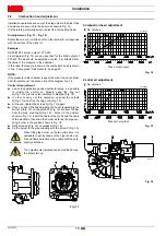
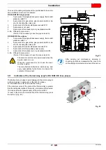
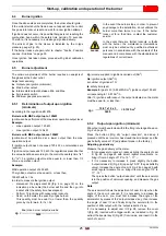
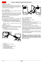
Fit a U-type pressure gauge (Fig. 25) to the gas pressure
test point on the pipe coupling.

Used to approximately calculate burner maximum output
using the Tab. F on page 20.

Connect two lamps or testers in parallel to the two gas line
solenoid valves VR and VS in order to check the exact
moment at which voltage is supplied. 
This operation is not required if each of the two solenoid
valves is equipped with a pilot light that signals voltage
passing through.

6.3

Burner start-up

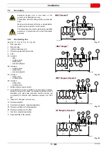
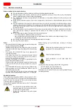
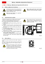
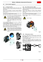
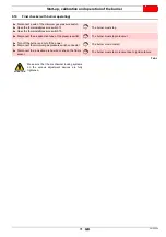
Turn off the remote controls and set the switch 1)(Fig. 26) to
“MAN”.
As soon as the burner starts, check the direction of rotation of the
fan impeller, looking through the flame inspection window 17)
(Fig. 4 on page 12).

6

Start-up, calibration and operation of the burner

ATTENTION

The first start-up of the burner must be carried out
by qualified personnel, as indicated in this manual
and in compliance with the standards and
regulations of the laws in force.

ATTENTION

Check the correct working of the adjustment,
command and safety devices.

ATTENTION

Before starting up the burner, refer to section
"Safety test - with no gas supply” on page 32.

CAUTION

Before starting up the burner, it is good practice to
adjust the gas train so that ignition takes place in
conditions of maximum safety, i.e. with gas
delivery at the minimum.

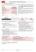
Fig. 25

D514

DANGER

Make sure that the lights or testers connected to
the solenoids, or the pilot lights on the solenoids
themselves, indicate that no voltage is present. 
If voltage is present, stop the burner immediately
and check the electrical connections.

Fig. 26

D3833

1

2

Содержание RS 25/M C05

Страница 1: ...2019 Forced draught gas burners Progressive two stage or modulating operation CODE MODEL TYPE 20159191 RS 25 M C05 S026T 20159192 RS 25 M C05 S026T 20159193 RS 35 M C05 S027T 20159194 RS 35 M C05 S02...

Страница 2: ...Translation of the original instructions...

Страница 3: ...x RMG M88 13 4 12 Servomotor SQN 14 5 Installation 15 5 1 Notes on safety for the installation 15 5 2 Handling 15 5 3 Preliminary checks 15 5 4 Operating position 16 5 5 Preparing the boiler 16 5 5 1...

Страница 4: ...out during operation 29 6 9 Burner start up cycle diagnostics 30 6 9 1 Resetting of control box and diagnostics use 30 6 9 2 Control box reset 30 6 9 3 Visual diagnostics 30 6 9 4 Software diagnostic...

Страница 5: ...12100 and according to the European Directives GAR 2016 426 EU Gas Appliances Regulation MD 2006 42 CE Machine Directive LVD 2014 35 EU Low Voltage Directive EMC 2014 30 EU Electromagnetic Compatibili...

Страница 6: ...ried out correctly may cause damage to the machine and or injury to people DANGER DANGER LIVE COMPONENTS This symbol indicates operations which if not carried out correctly lead to electric shocks wit...

Страница 7: ...vent of damage to things or injury to people if such damage injury was due to any of the following causes incorrect installation start up use and maintenance of the burner improper incorrect or unreas...

Страница 8: ...nance Only those parts envisaged by the manufacturer can be replaced 3 2 Personnel training The user is the person body or company that has acquired the machine and intends to use it for the specific...

Страница 9: ...al gas Oil Gas oil Methane Adjustment Flame control system FS1 FS2 Standard 1 stop every 24 hours Continuous working 1 stop every 72 h Electrical supply of the system 3 400 50 3 230 50 Voltage of auxi...

Страница 10: ...R B LU PL I2E Model RS 25 M C05 RS 35 M C05 Type S026T S027T Output 1 Max kW 125 340 108 295 200 440 190 380 Mcal h Min kW Mcal h 70 60 82 71 Fuel Natural gas G20 G25 G31 Pressure at maximum delivery...

Страница 11: ...x 25 No 4 Thermal flange gasket No 1 Screws to fix the burner flange to the boiler M 8 x 25 No 4 Plugs for electrical wiring No 3 RS 25 35 M C05 single phase Plugs for electrical wiring No 4 RS 35 M C...

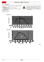
Страница 12: ...than the minimum limit of the diagram RS 25 M C05 70 kW RS 35 M C05 82 kW ATTENTION The firing rate value Fig 2 has been obtained considering an ambient temperature of 20 C an atmospheric pressure of...

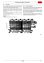
Страница 13: ...you can see the diameter and length of the test combustion chamber Example Output 400 kW diameter 50 cm length 1 5 m 4 9 1 Commercial boilers The burner boiler combination does not pose any problems...

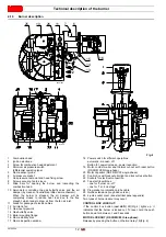
Страница 14: ...15 Boiler mounting flange 16 Flame stability disc 17 Flame inspection window 18 Power switch for different operations automatic manual off Button for power increase power reduction 19 Motor contact ma...

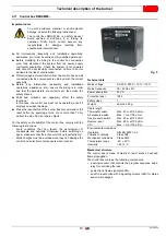
Страница 15: ...he development of condensate and humidity Otherwise before switching on again make sure that the entire control box is perfectly dry Static charges must be avoided since they can damage the control bo...

Страница 16: ...not allowed For safety reasons the servomotor must be checked after long periods of non use Technical data ATTENTION To avoid accidents material or environmental damage observe the following instructi...

Страница 17: ...side the boiler must be free from hazardous mixes e g chloride fluoride halogen if present it is highly recommended to carry out cleaning and maintenance more frequently ATTENTION Burner handling oper...

Страница 18: ...ested by the boiler manufacturer 5 5 3 Securing the burner to the boiler Separate the combustion head from the rest of the burner Fig 10 Remove the cover Disengage the articulated coupling 4 from the...

Страница 19: ...r must be airtight 5 7 Positioning the probe electrode If in the previous check the position of the probe or electrode was not correct remove the screw 1 Fig 11 extract the inner part 2 Fig 11 of the...

Страница 20: ...fy the central air delivery using the ring nut 4 Fig 13 up to the notch indicated in diagram Fig 15 In order to carry out this operation unscrew the screws 5 Fig 13 and lift up the ring nut 4 Fig 13 A...

Страница 21: ...over 1200 kW 9 Gasket for flanged versions only 10 Pressure adjuster 11 Train burner adaptor supplied separately P2 Pressure upstream of valves adjuster P3 Pressure upstream of the filter L Gas train...

Страница 22: ...gas G 25 NCV 8 13 kWh Sm3 7 0 Mcal Sm3 DANGER Disconnect the electrical power using the main switch Check that there are no gas leaks Pay attention when handling the train danger of crushing of limbs...

Страница 23: ...re at test point 1 Fig 22 15 6 mbar Pressure in combustion chamber 2 0 mbar 15 6 2 0 13 6 mbar A pressure of 13 6 mbar column 1 corresponds in table RS 35 M C05 to output of 360 kW This value serves a...

Страница 24: ...R The electrical wiring must be carried out with the electrical supply disconnected Electrical wiring must be made in accordance with the regulations currently in force in the country of destination a...

Страница 25: ...gas pressure switch 6 6A Fittings for pipe unions Pierce if it is necessary to use the pipe unions 6A 5 11 Calibration of the thermal relay only for RS 35 M C05 three phase The thermal relay is used t...

Страница 26: ...uipped with a pilot light that signals voltage passing through 6 3 Burner start up Turn off the remote controls and set the switch 1 Fig 26 to MAN As soon as the burner starts check the direction of r...

Страница 27: ...s Vg volume supplied in ignitions carried out Sm3 Qa ignition output Sm3 h n number of ignitions 10 ts safety time sec Example for gas G 20 9 45 kWh Sm3 ignition output 150 kW corresponding to 15 87 S...

Страница 28: ...ugh the access opening 6 Fig 27 Turn the screws clockwise to increase air delivery Turn the screws anti clockwise to reduce air delivery 1 Servomotor 2 Cam 4 engaged disengaged 3 Cam cover 4 Variable...

Страница 29: ...nd stage increase adjustment pressure by slowly turning the relevant knob clockwise until the burner stops Then turn the knob anticlockwise by 0 2 kPa 2 mbar and repeat burner start up to ensure it is...

Страница 30: ...ling the gas butterfly valve The servomotor rotates 90 in 24 s Do not alter the factory setting for the 4 cams just check that they are as specified below Cam I 90 Limits rotation toward maximum posit...

Страница 31: ...emperature or the pressure is low the reason why the thermostat pressure switch TR is in the output request posi tion the burner progressively increases the output up to the MAX value section C D Fig...

Страница 32: ...linked The number of blinks indicates the reason for the malfunctioning refer to the coding in Tab M on page 36 6 9 4 Software diagnostics Provides an analysis of the life of the burner through optica...

Страница 33: ...r must stop Disconnect the air adduction tube of the pressure switch The burner must stop in lockout Turn off the burner and cut off the power Disconnect the minimum gas pressure switch connector The...

Страница 34: ...that all components of the combustion head are in good condition not deformed by the high temperatures free of impurities from the surroundings and correctly positioned Gas filter Change the gas filt...

Страница 35: ...port Service to implement the necessary adjustments Tab K CO2 It is advisable to adjust the burner with a CO2 not greater than about 10 gas with Ncv 8600 kcal m3 In this way it is avoided that a small...

Страница 36: ...Reconnect the leads and slide in the burner until it comes to a stop Replace the screw 5 and carefully pull the probe and electrode cables outwards until they are slightly taut Re couple the articulat...

Страница 37: ...er does not switch on and the lockout appears Air pressure switch in operating position Adjust or replace The burner starts and then goes into lockout Air pressure switch does not switch owing to lack...

Страница 38: ...n Replace The burner continues to repeat the start up cycle without lockout The gas pressure in the gas mains lies very close to the value to which the gas pressure switch has been set The sudden drop...

Страница 39: ...Gas trains in compliance with EN 676 Please refer to manual Output power regulator kit for modulating operation A Appendix Accessories Burner Code All models 3010448 Burner Code All models 3002719 Bur...

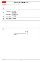
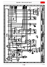
Страница 40: ...cation of references 3 Operational layout RS 25 M C05 RS 35 M C05 1 Ph RS 35 M C05 3 Ph 4 Operational layout RS 25 35 M C05 1 Ph RS 35 M C05 3 Ph 5 Electrical connections set by installer 6 Electrical...

Страница 41: ...39 20159324 GB Appendix Electrical panel layout 0 1 2 3 4 3 4 4 3 4 5 2 6 7899 3 9 6 7 6 3 86 9 7 6 739 6 8 A8 8 B 0 0 C C D D D E D F D D D D D D D D D D E D RS 25 M C05...

Страница 42: ...20159324 40 GB Appendix Electrical panel layout 0 1 2 3 2 3 3 2 3 4 567 6 8 1 9 6 2 9 9 72 69 9 2 9 6 A A B B B C C D D D E D F D D D D D D D D D D E D RS 35 M C05 1Ph...

Страница 43: ...41 20159324 GB Appendix Electrical panel layout 00 0 0 1 0 0 0 1 0 0 2 0 0 0 1 3 4 5 4 5 5 4 5 678 7 9 0 3 7 4 A 84 7 4 B 7 C C D D D E D F D D D D D D D D D D E D G 0 RS 35 M C05 3Ph...

Страница 44: ...20159324 42 GB Appendix Electrical panel layout RS 25 35 M C05 1Ph...

Страница 45: ...43 20159324 GB Appendix Electrical panel layout RS 35 M C05 3Ph...

Страница 46: ...8 7 E A FG C7 D 8 8 7 7 8 4 8 7 8 H E C7 D 8 A7 8 7 7 8 I7 A A7 8C 7 8 A A C7 A J D 3 3 3 3 0 1 0 1 3 3 3 8 7 4 E78 81 88 7 87D 8 E4 I7 88 7 8 D 8 H 4 7 8 88 7 8 D 8 C 8 8 4J 8 C 8D 3 K K K K L 0 0 0...

Страница 47: ...45 20159324 GB Appendix Electrical panel layout 0 1 2 13 4 5 4 2 6 6 1 6 1 7 6 6 1 6 1 1 6 6 6 6 6 06 0 0 6 6 1 7 6 1...

Страница 48: ...H 4 3 8 7 H 1 1 0 0 B 6 C 5 7 4 B 6 3C 0 5 7 4 B 6 C 5 1 2 34 A 5 5 B 6 C 54 5 4 45 5 4 4 7 4 1 1 4 4 7 4 4 4 B7C 4 B 6 C 5 5 45 5 44 B C 4 5 45 0 I 0 A 0 A 0 A 0 I A A A 1 9 6 I A 6 A J 0 A I A A A K...

Страница 49: ...witch ION Ionisation probe h1 Hour counter K1 Relay KM Motor contact maker MV Fan motor PA Air pressure switch PGM Maximum gas pressure switch PGMin Low gas pressure switch Q1 Three phase knife switch...

Страница 50: ......

Страница 51: ......

Страница 52: ...Subject to modifications RIELLO S p A I 37045 Legnago VR Tel 39 0442 630111 http www riello it http www riello com...

Отзывы: