27
20034293
GB
Start-up, calibration and operation of the burner
6.1
Notes on safety for the first start-up
6.2
Adjustment before first firing (gas oil operation)
6.2.1
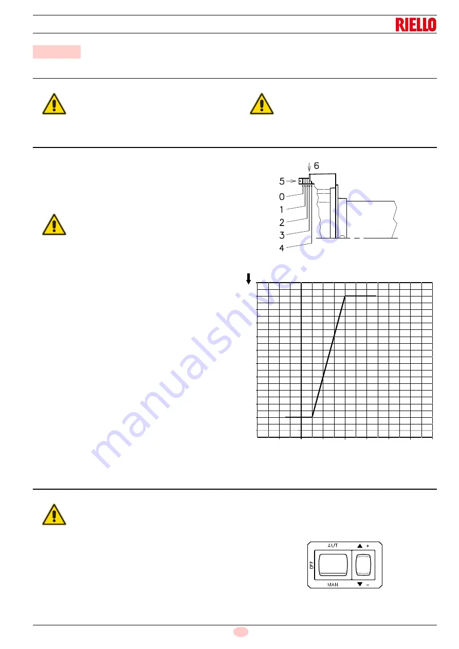
Combustion head setting
The setting of the combustion head depends exclusively on the
maximum burner output.
Turn screw 5)(Fig. 29) until the notch shown in diagram (Fig. 30)
is level with the front surface of flange 6).
Example:
Maximum burner output = 1500 kW.
If diagram (Fig. 30) is consulted it is clear that for this delivery, the
combustion head must be adjusted using notch 4, as shown in
Fig. 29.
6.2.2
Pump adjustment
No settings are required for the pump, which is set to 12 bar by
the manufacturer. This pressure must be checked and adjusted
(if required) after the burner has been ignited.
The only operation required in this phase is the application of a
pressure gauge on the appropriate pump attachment.
6.2.3
Fan gate adjustment
The first time the burner is fired leave the factory setting un-
changed for both 1
st
stage and 2
nd
stage operation.
6.3
Burner calibration (gas oil operation)
6.3.1
Firing
Set switch 1)(Fig. 31) to "MAN".
During the first firing, during the passage from the 1
st
to the 2
nd
stage, there is a momentary lowering of the fuel pressure caused
by the filling of the 2
nd
stage nozzle tubing.
This lowering of the fuel pressure can cause the burner to lock-
out and can sometimes give rise to pulsations.
Once the following adjustments have been made, the firing of the
burner must generate a noise similar to the noise generated dur-
ing operation.
6
Start-up, calibration and operation of the burner
WARNING
The first start-up of the burner must be carried out
by qualified personnel, as indicated in this manual
and in compliance with the standards and regula-
tions of the laws in force.
WARNING
Check the correct working of the adjustment, com-
mand and safety devices.
WARNING
In order to facilitate adjustment, loosen screw
1)(Fig. 11 at page 17), adjust and then tighten.
Fig. 29
D1149
6
5
4
3
2
1
0
1000
0
1
2
3
4
5
6
1500
2000
2500
3000
3500
kW
7
500
0
8
9
10
Fig. 30
Notches no.
D3948
Max burner output
WARNING
It is advisable to first set the burner for operating
on oil and then for gas.
Execute the fuel exchange when the burner is off.
Fig. 31
1
2
D791
Содержание RLS 250/M
Страница 2: ...Original instructions ...
Страница 45: ...43 20034293 GB Appendix Electrical panel layout ...
Страница 46: ...20034293 44 GB Appendix Electrical panel layout ...
Страница 47: ...45 20034293 GB Appendix Electrical panel layout ...
Страница 48: ...20034293 46 GB Appendix Electrical panel layout ...
Страница 49: ...47 20034293 GB Appendix Electrical panel layout ...
Страница 51: ......


