


15
STATUS
Accessory available on request.
See page 16.
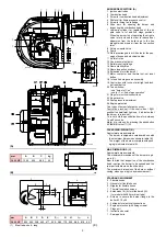
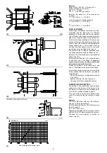
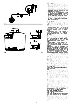
ASSEMBLY
The burners are preset to accept the Status. To
assemble, proceed as follows:
- Connect Status 1) using connector 2) fitted on
the bracket 3).
- Fix the support 5) to the Status using the
screws 4) supplied in the kit.
- Fix the assembly to the shelf 3) using the
screws 6).
The
STATUS
unit has three functions:
1 - BURNER OPERATING HOURS AND THE
NUMBER OF FIRINGS ARE SHOWN ON
DISPLAY V
Total operating hours
Press button "h1".
2nd stage operating hours
Press button "h2".
1st stage operating hours
Total hours - 2nd stage operating hours
Number of firings
Press button "count".
Resetting operating hours and number of fir-
ings
Press the three “reset” buttons simultaneously.
Non-volatile memory
The operating hours and the number of firings
will remain in the memory even in the case of
electrical power failures.
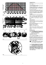
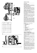
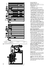
2 - INDICATES THE TIMES RELATIVE TO THE
FIRING STAGE
The leds illuminate in the following sequence,
see fig. A:
WITH CONTROL DEVICE TR CLOSED:
1 - Burner off, TL open
2 - Control device TL closed
3 - Motor start:
seconds count starts on read-out V
4 - 1st stage valve energized
5 - 2nd stage valve energized:
seconds count stops on read-out V
6 - 10 seconds after stage 5 the code I I I I
will appear on the read-out: this indicates
that the starting phase is terminated.
WITH CONTROL DEVICE TR OPEN:
1 - Burner off, TL open
2 - Control device TL closed
3 - Motor start:
seconds count starts on read-out V
4 - 1st stage valve energized
7 - 30 seconds after stage 4:
seconds count stops on read-out V
8 - 10 seconds after stage 7 the code I I I I
will appear on the read-out: this indicates
that the starting phase is terminated.
The times, in seconds, shown on read-out V,
indicate the succession of the various starting
stages described on page 10.
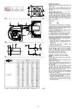
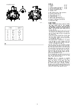
3 - IN THE CASE OF BURNER MALFUNC-
TIONS, THE STATUS PANEL INDICATES
THE EXACT TIME AT WHICH THE FAULT
OCCURRED.
There are 3 possible combinations of illumi-
nated leds, see fig. (B).
For the causes of the malfunction refer to the
numbers shown between brackets; see the
legend on page 14 for interpretation of the
numbers.
1 . . . . . . . . . . . (9 ÷ 10)
2 . . . . . . . . . . . (11 ÷ 29)
3 . . . . . . . . . . . (32)
Key to symbols:
= Power present
= Fan motor blocked (red)
= Burner lock-out (red)
= Not used
= 1st stage operation
= Load level reached (Stand-by), led:
on
(A)
Led flashing
Led illuminated
Time in seconds
Burner start cycle terminated
STATUS
(optional)
1
2
3
4
6
5
1 Status
2 Connector
3 Bracket of the burner
4 Fixing screws
5 Support
6 Fixing screws
D3995
Assembly
D478