background image


2136


4


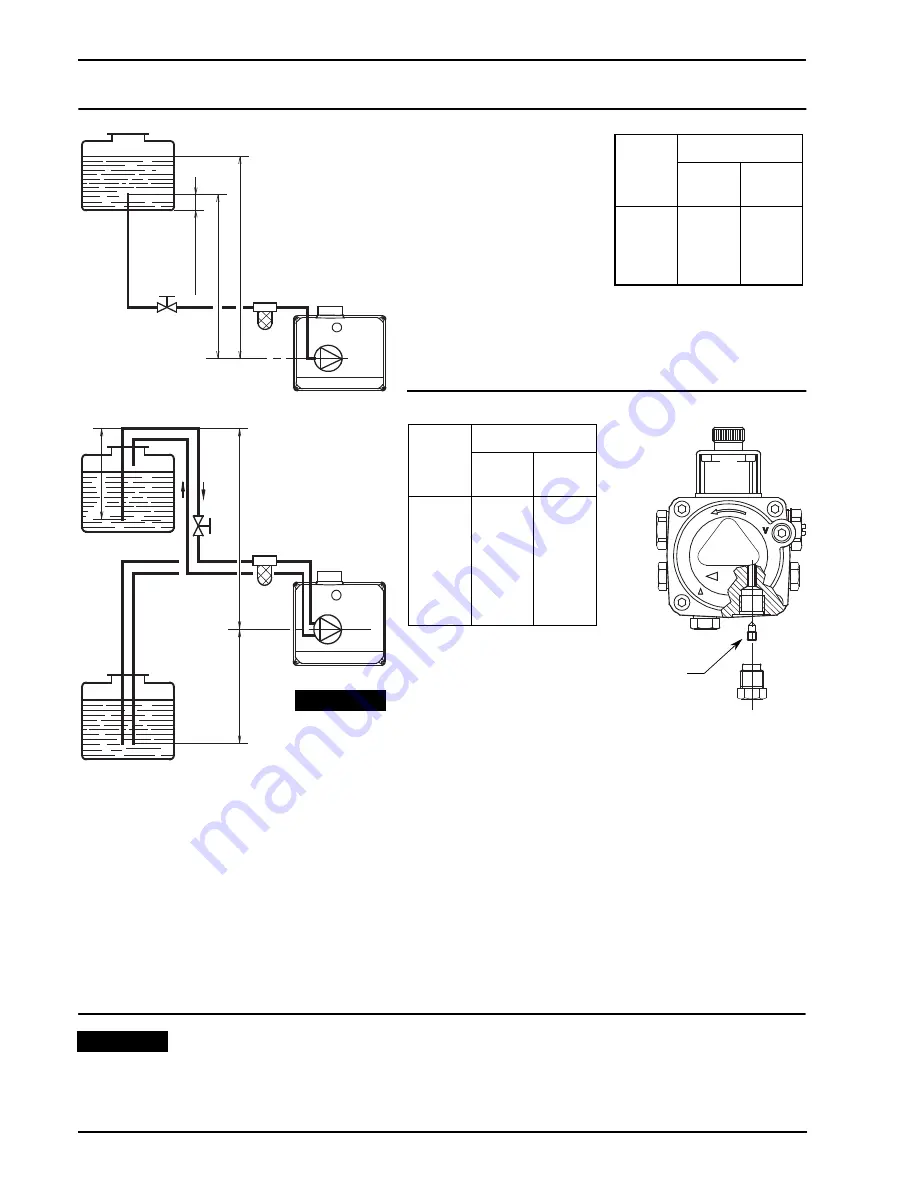
OIL LINES 

H

meters

L meters

I. D.

8 mm

I.D.

10 mm

0.5

1

1.5

2

10
20
40
60

20
40
80

100

PRIMING THE PUMP
Loosen the plug of the vacuum gauge (4, fig. 1, page 1)
and wait until the fuel flows out.

H

meters

L meters

I. D.

8 mm

I.D.

10 mm

0

0.5

1

1.5

2
3

3.5

35
30
25
20
15

8
6

100
100
100

90
70
30
20

max.

 4 m

H

H

max.

 4 m

min.

 0.1 m

D5307

D5308

H

The pump vacuum should not exceed a maximum of 0.4 bar (30 cm Hg). Beyond this limit gas is released
from the oil. Oil lines must be completely airtight. The return line should terminate in the oil tank
at the same level as the suction line
; in this case a non-return valve is not required.  
Should however the return line arrives over the fuel level, the non-return valve is indispensable. 
This solution however is less safe than previous one, due to the possibility of leakage of the valve.

PRIMING THE PUMP: 
Start the burner and wait for the priming. Should lock-out occur prior to the arrival of the fuel, await at
least 20 seconds before repeating the operation.

WARNING: Before starting the burner make sure that the return pipe-line is not clogged: any

obstruction would cause the pump seals to break.


Check periodically the flexible pipes conditions. 
Using kerosene, they have to be replaced at least every 2 years.

A metal bowl filter with replaceable micronic filter must be fitted in the oil supply pipe.

 WARNING

A

D5199


The pump is supplied for use with a one pipe system. 
For use on a two pipes system, it is  necessary to screw the
BY-PASS SCREW (A) supplied with kit code 3000970.

 WARNING

=

Difference of level.

L

= Max. 

length of the suction line.

I.D. =

Internal diameter of the oil pipes.

Содержание G3BF 490T53

Страница 1: ...2902136 6 Installation use and maintenance instructions Kerosene burners One stage operation CODE MODEL TYPE 3749053 G3BF 490T53 3749257 G5BF 492T57 3748953 G5BF 489T53...

Страница 2: ......

Страница 3: ...rner with CE marking in conformity with EEC directives EMC89 336 EEC Low Voltage 73 23 EEC Machines 89 392 EEC and Efficiency 92 42 EEC The intake air temperature must not be over 70 C The burner meet...

Страница 4: ...ange Nuts for flange TYPE A B C D E F G H I 490 T53 271 249 288 193 90 93 207 75 21 492 T57 271 249 288 191 90 93 226 75 26 489 T53 271 249 288 191 89 79 237 75 37 Flange Burner C F G 130 I 4 5 E A 11...

Страница 5: ...power kW D5426 25 30 35 0 2 0 6 0 6 0 0 2 0 4 Pressure in the combustion chamber mbar 1 5 2 2 5 Fuel output kg h 20 25 30 Thermal power kW D5425 0 8 0 0 4 Pressure in the combustion chamber mbar 2 3 4...

Страница 6: ...indispensable This solution however is less safe than previous one due to the possibility of leakage of the valve PRIMING THE PUMP Start the burner and wait for the priming Should lock out occur prio...

Страница 7: ...owards the arrow The photoresistance is fitted directly into the control box underneath the ignition transformer on a plug in support TESTING Check the shut down of the burner by opening the thermosta...

Страница 8: ...ed of excess air etc All these conditions may require a different air damper setting NOZZLES RECOMMENDED Monarch type R NS Delavan type W A E B Steinen type Q H Danfoss type B H S Angle 60 in most cas...

Страница 9: ...TO THE RIGHT sign In order to increase the volume of air entering the combustion chamber and thus diminishing its pres sure There is a reduction of CO2 and the adhesion of the flame to the air diffus...

Страница 10: ...below ELECTRODE SETTING BURNER START UP CYCLE 3 1 2 3 D5141 Turn to the right sign to increase the air quantity in the combustion chamber turn to the left sign to decrease it S7021 Attention Before as...

Страница 11: ......

Страница 12: ......

Отзывы: