


Information and general instructions
3
20026767
1.1
Information about the instruction manual
1.1.1
Introduction
The instruction manual supplied with the burner:
is an integral and essential part of the product and must not be
separated from it; it must therefore be kept carefully for any
necessary consultation and must accompany the burner even
if it is transferred to another owner or user, or to another sys-
tem. If the manual is lost or damaged, another copy must be
requested from the Technical Assistance Service of the area;
is designed for use by qualified personnel;
offers important indications and instructions relating to the
installation safety, start-up, use and maintenance of the
burner.
Symbols used in the manual
In some parts of the manual you will see triangular DANGER
signs. Pay great attention to these, as they indicate a situation
of potential danger.
1.1.2
General dangers
The
dangers
can be of
3 levels
, as indicated below.
1.1.3
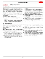
Safety precautions
Good safety practices must be used when working on burner
equipment. The potential energy in the electrical supply, fuel and
related equipment must be handled with extreme care to prevent
equipment failures, injuries and potential death.
1.1.4
Danger: live components
Other symbols
This symbol indicates a list.
Abbreviations used
Ch.
Chapter
Fig.
Figure
Pag.
Page
Sec.
Section
Tab.
Table
Delivery of the system and the instruction manual
When the system is delivered, it is important that:
The instruction manual is supplied to the user by the system
manufacturer, with the recommendation to keep it in the room
where the heat generator is to be installed.
The instruction manual shows:
– the serial number of the burner;
– the address and telephone number of the nearest Assis-
tance Centre;
The system supplier carefully informs the user about:
– the use of the system,
– any further tests that may be necessary before the system is
started up,
– maintenance and the need to have the system checked at
least once a year by the manufacturer or another specialised
technician.
To ensure a periodic check, the manufacturer recommends
the drawing up of a Maintenance Contract.
1
Information and general instructions
DANGER
Maximum danger level!
This symbol indicates operations which, if not car-
ried out correctly,
cause
serious injury, death or
long-term health risks.
WARNING
This symbol indicates operations which, if not car-
ried out correctly,
may cause
serious injury, death
or long-term health risks.
CAUTION
This symbol indicates operations which, if not car-
ried out correctly,
may cause
damage to the ma-
chine and/or injury to people.
WARNING
If you smell gas, open window, extinguish any open
flames, stay away from electrical switches, evacu-
ate the building and immediately call the gas com-
pany.
If this equipment is not installed, operated, operated
and maintained in accordance with the manufactur-
ers intructions, this product could expose you to
substances in fuel or from fuel combustion which
can cause death or serious illness.
Improper servicing of this equipment may create a
potential hazard to equipment and operators.
Servicing must be done by a fully trained and
qualified personnel.
DANGER
This symbol indicates operations which, if not car-
ried out correctly, lead to electric shocks with lethal
consequences.
ENVIRONMENTAL PROTECTION
This symbol gives indications for the use of the ma-
chine with respect for the environment.
............................................................................................
...........................................................................................
...........................................................................................
...........................................................................................
Содержание C9541400
Страница 2: ......
Страница 30: ...20026767 28 Appendix Spare parts A Appendix Spare parts...
Страница 35: ......


