


Start-up, calibration and operation of the burner
29
2916050
GB
5.4.1
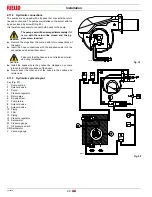
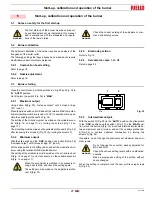
Cams and trim potentiometers functions
Cam 1:
130°
Limits rotation towards maximum
Cam 2:
0°
Limits rotation towards minimum, air damper closed on stand by
Cam 3:
20°
Limits ignition position
Cams 4 - 5 - 6 - 7 - 8
: not used
Trim potentiometer MAX
Limits maximum modulation. It must be set near the stroke end
(cam 1) to exploit as far as possible the variable profile cam.
Trim potentiometer MIN
Limits minimum modulation. It must be set near the stroke end
(cam 2) to exploit as far as possible the variable profile cam.
Trim potentiometer POS
Limits an intermediate operating position between MAX and MIN,
supplying power to the “P” terminal in the servomotor (through an
external command). This function cuts out any external signals.
NOTE:
using the slide switch (Fig. 38) to select MAX or MIN, the ser-
vomotor goes into the position for the respective settings of
the MAX and MIN TRIM POTENTIOMETERS.
When the settings are complete, place the slide switch on “
OPE
”
(operate).
5.5
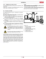
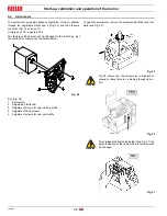
Final calibration of the pressure switch
5.5.1
Air pressure switch
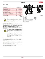
Adjust the air pressure switch after having performed all other burn-
er adjustments with the air pressure switch set to the start of the
scale (B).
With the burner operating at min. output, increase adjustment pres-
sure by slowly turning the relative dial clockwise until the burner
locks out.
Then turn the dial anti-clockwise by about 20% of the set point and
repeat burner starting to ensure it is correct.
If the burner locks out again, turn the dial anti-clockwise a little bit
more.
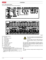
Slide switch
Trim potentiometers
Position jumpers
Fig. 38
D2593
B
C
A
Fig. 39
D2548


