


Technical description of the burner
9
2916050
GB
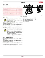
3.7
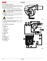
Burner description
1
Ignition electrodes
2
Combustion head
3
Screw for combustion head adjustment
4
Screw for fixing fan to flange
5
Pressure gauge for pressure on nozzle return
6
Pump
7
Non-drip nozzle holder
8
Air damper
9
Fan pressure test point
10 Boiler mounting flange
11 Flame stability disk
12 Servomotor, provides adjustment of fuel delivery regulator
and of air damper.
When the burner is not operating the air damper is fully closed
in order to reduce to a minimum heat dispersion from the
boiler.
13 Slide bars for opening the burner and inspecting the combus-
tion head
14 Photocell (cad cell)
15 High oil pressure switch
16 Extensions for slide bars 14) (with kit)
17 Ignition transformer
18 Motor contactor and thermal overload with reset button
19 Power switch for different operations: automatic - manual - off
Button for: power increase - power reduction
20 Valve assembly with pressure regulator on nozzle return
21 Terminal strip
22 Knockouts for electrical connections by installer
23 Flame safeguard with lock-out pilot light and lock-out reset
button
24 Flame inspection window
Two types of burner failure may occur:
Flame safeguard lock-out
: if the flame relay 23)(Fig. 3)
pushbutton lights up, it indicates that the burner is in lock-out.
To reset, press the pushbutton.
Motor trip
: release by pressing the pushbutton on thermal
overload 18)(Fig. 3).
Fig. 3
D2349


