


8
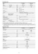
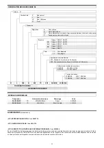
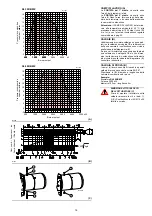
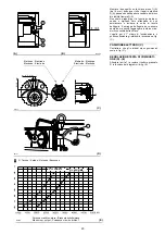
TECHNICAL DATA
(1)
Reference conditions: Ambient temperature 20°C - Barometric pressure 1000 mbar - Altitude 100 m a.s.l.
(2)
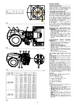
Pressure at pressure switch test point 20)(A)p.12 with zero pressure in the combustion chamber and maximum burner output.
(3)
Sound pressure measured in manufacturer's combustion laboratory, with burner operating on test boiler and at maximum rated output. The
sound power is measured with the “Free Field” method, as per EN 15036, and according to an “Accuracy: Category 3” measuring accuracy, as
set out in EN ISO 3746.
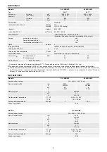
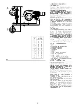
ELECTRICAL DATA
Model
RL 300/B MZ
RL 400/B MZ
Type
966 T
967 T
Output
(1)
Delivery
(1)
2nd stage
(min - max)
kW
kg/h
1250 ÷ 3550
105 ÷ 301
2000 ÷ 4450
169 ÷ 378
1st stage
(min)
kW
kg/h
600
50
1000
84
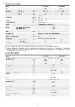
Fuel
LIGHT OIL
- net calorific value
kWh/kg
Mcal/kg
11.8
10.2 (10.200 kcal/kg)
- density
kg/dm
3
0.82 - 0.85
- viscosity at 20 °C
mm
2
/s
max 6 (1.5 °E - 6 cSt)
Operation
- Intermittent (min. 1 stop in 24 hours)
- Two-stage (high and low flame) and single-stage (all - nothing)
Pump
delivery at 20 bar (kg/h)
pressure range (bar)
fuel temperatur (°C)
380
7 - 40
140
Nozzles
number
2
Standard applications
Boilers: water, steam, diathermic oil
Ambient temperatur
°C
0 - 40
Combustion air temperature
°C max
60
Conformity to directives
2014/30/UE - 2014/35/UE - 2006/42/EC
Noise levels
(3)
Sound pressure
Sound power
dBA
83
94
85
96
Approval
class 2 (EN 267)
CE
Model
RL 300/B MZ
RL 400/B MZ
Electrical supply
3N ~ 400V +/-10% 50 Hz
Fan motor IE2
rpm
V
kW
A
2900
230/400
4.5
15/8.7
2900
400/690
7.5
13.8/8
Pump motor
V
kW
A
220/380
1.1
4.5 - 2.6
Ignition transformer
V1 - V2
I1 - I2
230 V - 2 x 5 kV
1.9 A - 35 mA
Electrical power consumption
kW max
7
10.6
Electrical protection
IP 54
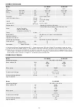
Model
RL 400/B MZ
Electrical supply
3N ~ 400V +/-10% 50 Hz
Fan motor IE3
rpm
V
kW
A
2920
400/690
7.5
14/8.1
Pump motor
V
kW
A
220/380
1.1
4.5 - 2.6
Ignition transformer
V1 - V2
I1 - I2
230 V - 2 x 5 kV
1.9 A - 35 mA
Electrical power consumption
kW max
10.6
Electrical protection
IP 54
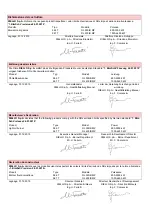
Содержание 966 T
Страница 43: ...43 0 1 2 30 0 0 1 2 30 0 1 2 2 4 4 0 4 0 5 4 6 4 0 4 0 0 4 4 4 4 4 74 7 7 4 4 0 5 4 0 0 0 0 0 0 0 RL 300 B MZ...
Страница 45: ...45 RL 300 B MZ...
Страница 46: ...46 RL 400 B MZ...
Страница 47: ...47...
Страница 48: ...48 RL 300 B MZ...
Страница 49: ...49 0 1 1 1 2 3 2 RL 400 B MZ...
Страница 50: ...50 01123 0 3 112 01453 6 7 0 3 8 9 0 3 112 01453 6 7 8 9 8 8 9 8 9 76 76 A...
Страница 53: ......
Страница 54: ......
Страница 55: ......


