background image

F10 -  13

COMBUSTION CHAMBER

Follow the instructions furnished by the boiler/furnace manufacturer. Size retrofit
application according to the appropriate installation codes (eg. CSA B139 or NFPA #31).

NON-RETROFIT APPLICATIONS

If this burner is being installed in a packaged unit (ie. burner comes with a boiler or
furnace), follow the installation and set-up instructions supplied with the heating unit,
as settings will differ from those shown in this manual.

Содержание 40 F10

Страница 1: ...with the heating unit as settings may differ from those shown in this manual The following pages contain information descriptions and diagrams for the proper installation and wiring of the burner Please read carefully before attempting final installation This manual is to remain with the final installation designation It is the installer s responsibility to en sure that the burner installation and...

Страница 2: ...ION FIELD WIRING 6 NOZZLE PLACEMENT 7 INSERTION REMOVAL OF DRAWER ASSEMBLY 7 ELECTRODE SETTING 8 TURBULATOR SETTING 8 OIL LINE CONNECTIONS 8 Single Line Gravity Feed System 9 Two Line Lift System 10 PUMP PURGE 11 Single Line Gravity Feed System 11 Two Line Lift System 11 SETTING THE AIR ADJUSTMENT PLATE 12 BURNER SET UP CHART 12 PRECAUTIONS CANADA 14 PRECAUTIONS U S A 15 SPARE PARTS 16 QTY DESCRIP...

Страница 3: ...BSORBED ELECTRICAL POWER 230 Watts MOTOR rated 3250 rpm Run Current 2 2 AMP CAPACITOR 12 5 Microfarads 260V PUMP PRESSURE 100 to 200 PSI PRIMARY CONTROL RIELLO 530 SE C IGNITION TRANSFORMER 8kV 16 mA MOUNTING FLANGE DIMENSIONS MODEL F10 A B C D E F Inches 10 5 16 12 8 1 32 3 15 16 5 10 7 16 mm 262 305 204 100 127 265 MODEL F10 A B C D Inches 1 1 4 1 4 7 16 2 3 16 mm 32 6 11 56 D6012 B E F A C D E1...

Страница 4: ...trol box and air tube cover see page 7 C Remove drawer assembly from air tube insert nozzle and set turbulator adjustment for specific input required see pages 7 8 then set aside D Mount air tube to burner chassis see page 3 D6178 1 2 3 4 5 7 8 18 16 15 14 12 11 10 17 9 13 6 1 Lockout indicator lamp and Reset button 2 Primary control 3 Primary control sub base 4 Pump pressure regulator adjustment ...

Страница 5: ...RNER CHASSIS FRONT PLATE when the BOLTS 3 were removed Replace the BOLTS and finger tighten only Re install DRAWER ASSEMBLY into AIR TUBE Tighten SCREW 2 securely see page 7 D Tighten the two bolts 3 securely MOUNTING THE BURNER TO THE BOILER OR FURNACE There are three possible methods to mount the burner depending on the individual application These are 1 Universal flange bolted to Boiler Furnace...

Страница 6: ...B at right The measured length A is to include MOUNTING GASKET and FLANGE if used D The burner may now be attached to the heating unit by inserting the AIR TUBE through the BURNER ACCESS HOLE 8 and into the appliance making sure the BOLTS 1 line up with the two HOLES 5 in the ADJUSTABLE COLLAR Secure the burner in place using two NUTS 7 A visual verification of the air tube insertion into the comb...

Страница 7: ...1 items A C and D NOTE It is suggested that the pedestal be anchored in position on the floor by installing brackets over the pedestal tube and securing brackets to the floor ELECTRICAL CONNECTIONS It is advisable to leave the control box off the sub base while completing the electrical connections to the burner WARNING WHEN THE COMBUSTION CHAMBER IS LINED WITH A REFRAC TORY MATERIAL IT IS IMPERAT...

Страница 8: ...e SUB BASE Should lockout occur the 530SE CONTROL BOX will supply a power source of 120Vac to the con nection terminal The maximum allowable current draw on this terminal 4 is 1 Amp WARNING DO NOT activate burner until proper oil line connections have been made or failure of the pump shaft seal may occur WARNING If a neutral or ground lead is attached to this terminal the CONTROL BOX on the burner...

Страница 9: ...he NOZZLE ADAPTER and tighten securely Do not overtighten D Replace adapter with nozzle installed into drawer assembly and secure with screw 1 INSERTION REMOVAL OF DRAWER ASSEMBLY A To remove drawer assembly loosen SCREW 3 then unplug CONTROL BOX 1 by carefully pulling it back and then up B Remove the AIR TUBE COVER PLATE 5 by loosening the two retaining SCREWS 4 C Loosen SCREW 2 then slide the co...

Страница 10: ...em with the by pass plug installed Operating a single line system with the by pass plug installed will result in damage to the pump shaft seal Note Pump pressure must be set at time of burner start up A pressure gauge is attached to the PRESSURE PORT 8 for pressure readings Two PIPE CONNECTORS 5 are supplied with the burner for connection to either a single or a two pipe system Also supplied are t...

Страница 11: ...If the pump cover 1 is removed for any reason be sure the O ring 2 is properly seated in the pump cover 1 before re attaching the pump cover to the pump housing B Connect the pipe connector to the SUPPLY PORT 6 of the pump Attach the required piping to this pipe connector Be sure that the plug in the RETURN PORT 9 is tightened securely 6 5 4 8 2 3 1 4 D6179 9 SINGLE LINE SYSTEM PIPE LENGTHS H 3 8 ...

Страница 12: ... 2 Install the by pass plug 4 using the 2 5 mm hexagonal key B Attach the two PIPE CONNECTORS 5 to the pump SUPPLY and pump RETURN PORTS 6 and 9 Attach the required piping to these two pipe connectors using the NPT METRIC ADAPTERS that are supplied with the burner WARNING Pipe dope or Teflon tape are NOT to be used on any direct oil con nection to the fuel pump WARNING The height P in Pipe Length ...

Страница 13: ...er until the fuel pump has been purged of air then tighten the bleeder valve and immediately shut down the burner 8 Reinstall the air tube cover and nozzle line 9 The burner can now be started normally WARNING Omitting steps 2 and 3 will result in a collection of unburned oil in the com bustion chamber creating a hazardous situation upon burner startup B TWO LINE LIFT SYSTEM Turn off the main powe...

Страница 14: ...smoke reading of zero NOTE Variations in flue gas smoke CO2 and temperature readings may be experienced when the burner cover is put in place Therefore the burner cover must be in place when making the final combustion instrument readings to ensure proper test results BURNER SET UP CHART NOZZLES Monarch R PLP Delavan W B Danfoss S B Steinen SS S Hago P NOTE A 60 degree nozzle is suggested however ...

Страница 15: ...ccording to the appropriate installation codes eg CSA B139 or NFPA 31 NON RETROFIT APPLICATIONS If this burner is being installed in a packaged unit ie burner comes with a boiler or furnace follow the installation and set up instructions supplied with the heating unit as settings will differ from those shown in this manual ...

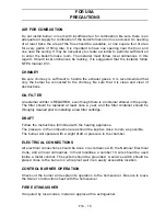
Страница 16: ... FILTER An external oil filter is REQUIRED even though there is an internal strainer in the pump The filter should be replaced at least once a year and the filter container should be thoroughly cleaned prior to installing a new filter cartridge DRAFT Follow the instructions furnished with the heating appliance The pressure in the combustion area should be kept as close to zero as possible The burn...

Страница 17: ...L FILTER An external oil filter is REQUIRED even though there is an internal strainer in the pump The filter should be replaced at least once a year and the filter container should be throughly cleaned prior to installing a new filter cartridge DRAFT Follow the instructions furnished with the heating appliance The pressure in the combustion area should be kept as close to zero as possible The burn...

Страница 18: ...F10 16 SPARE PARTS ...

Страница 19: ... 27 3005854 Semi Flange 28 3005855 Universal Mounting Flange 29 3005856 Mounting Gasket 30 3005788 Fan 31 3005844 Capacitor 12 5 µF 32 3007357 Acoustic Liner 33 3007205 Manual Air Shutter 34 3007209 Air Intake Housing 40 3949071 Short Combustion Head 5 273T1 41 3006978 Turbulator Disc 42 3006966 Electrode Support 43 3006965 Nozzle Adapter 44 3006979 Nozzle Oil Tube Short 45 3005888 Regulator assem...

Страница 20: ...0 474 3556 35 Pond Park Road Hingham MA 02043 Phone 781 749 8292 Toll Free 800 992 7637 Fax 781 740 2069 www riellousa com 2165 Meadowpine Blvd Mississauga ON L5N 6H6 Phone 905 542 0303 Toll Free 800 387 3898 Fax 905 542 1525 www riellocanada com ...

Отзывы: