


6
r
RTS 3S
steel boilers are high efficiency triple flue
pass boilers for central heating systems. When com-
bined with a storage cylinder, they can also be used to
produce domestic hot water.
r
RTS 3S
boilers are monobloc boilers with pressur-
ised combustion. The flame from the burner first enters
the furnace (1st flue pass). Via an opening at the other
end of the furnace, the combustion gases then enter a
duct that takes them back towards the front of the boiler
(2nd flue pass).
This separation between the combustion gas return duct
and the furnace makes a major contribution to reducing
Nox emissions. Combustion gases remaining in the high
temperatures of the furnace is one of the main reasons
for the formation of NOx emissions.
At the front of the boiler, the combustion gases pass
through a recess in the door insulation and exit through
the tube bundle (3rd flue pass).
In the tube bundle, turbulators force the combustion
gases into a vortex-like path that improves the efficiency
of convection heat exchange.
This system achieves maximum heat absorption without
risking damage through thermal stress.
Once out of the tube bundle, the flue gases pas through
a chamber at the rear of the boiler, and into the vent flue.
Their special design (with tube bundle over the combus-
tion chamber) makes these boilers far narrower than
conventional pressurised boilers and therefore easier to
install in boiler rooms with narrow doors or where space
is limited.
The burner is installed in a hinged door to permit the
adjustment and servicing of both boiler and burner with-
out having to remove the burner.
The boiler body is thermally insulated by high efficiency
mineral wool insulation that reduces heat loss to an
extremely low level.
The boiler casing is made from pre-painted panels lined
with mineral wool insulation.
Max. permissible return temperature with a gas burner:
50°C.
Max. permissible return temperature with a fuel oil
burner: 37°C.
1
2
3
4
5
6
7
8
9
10
13
11
12
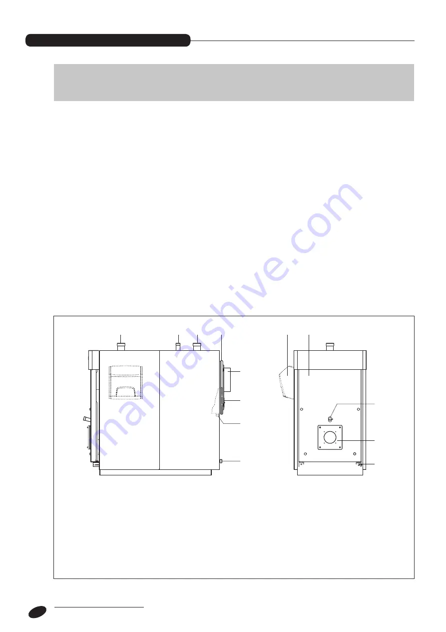
1 - Door hinge
2 - Central heating return
3 - Central heating flow
4 - Safety device fitting
5 - Flue gas box
6 - Flue gas exhaust
7 - Access door for cleaning the flue gas box
8 - Condensate drain
9 - Boiler drain
10 - Door
11 - Flame inspection window
12 - Burner plate
13 - Control panel
Product description
PRODUCT DESCRIPTION
MODELS UP TO 400 KW USED WITH FUEL OIL BURNERS CONFORM TO THE ENERGY-RELATED PRODUCTS
DIRECTIVE 2009/125/EC AND TO THE EU DELEGATED REGULATION 813/2013
GENERAL


