background image

2305

6

GB

4.

WORKING

4.1

COMBUSTION ADJUSTMENT

In conformity with Efficiency Directive 92/42/EEC the application of the burner on the boiler, adjustment and
testing must be carried out observing the instruction manual of the boiler, including verification of the CO and CO

2

concentration in the flue gases, their temperatures and the average temperature of the water in the boiler.
To suit the required appliance output, choose the proper nozzle and adjust the pump pressure, the setting of
the combustion head, and the air damper opening in accordance with the following schedule.
Values in the table refer to 12% CO

2

 and to sea level.


RECOMMENDED


NOZZLES

Monarch type R,

Delavan type W - E,

Steinen type Q,

Danfoss type S,

Satronic type S.

MAINTENANCE POSITION

Nozzle
 

Pump pressure

Burner output

Comb. head

adjustment

Air damper

adjustment

bar

kg/h ± 4%

1st stage

2nd stage

GPH

Angle

1st stage

2nd stage

1st stage

2nd stage

Set-point

Set-point

Set-point

0.40

80°

9

14

1.3

1.7

0.3

0

0.6

0.50

60° / 80°

9

14

1.7

2.1

1

0

0.9

0.60

60°

9

14

2.0

2.5

1.3

0.1

1.3

0.65

60° / 45°

9

14

2.2

2.7

1.5

0.2

1.7

0.75

60° / 45°

9

14

2.5

3.1

2

0.4

2.2

0.85

45°

9

14

2.8

3.5

3

0.5

2.7

1.00

45°

9

14

3.3

4.2

4

0.7

3.8

1.10

45°

9

14

3.7

4.6

5

0.8

4

1.25

45°

9

13

4.2

5.0

6

1

6

1

2

1

Fig. 11

S7197

S7184

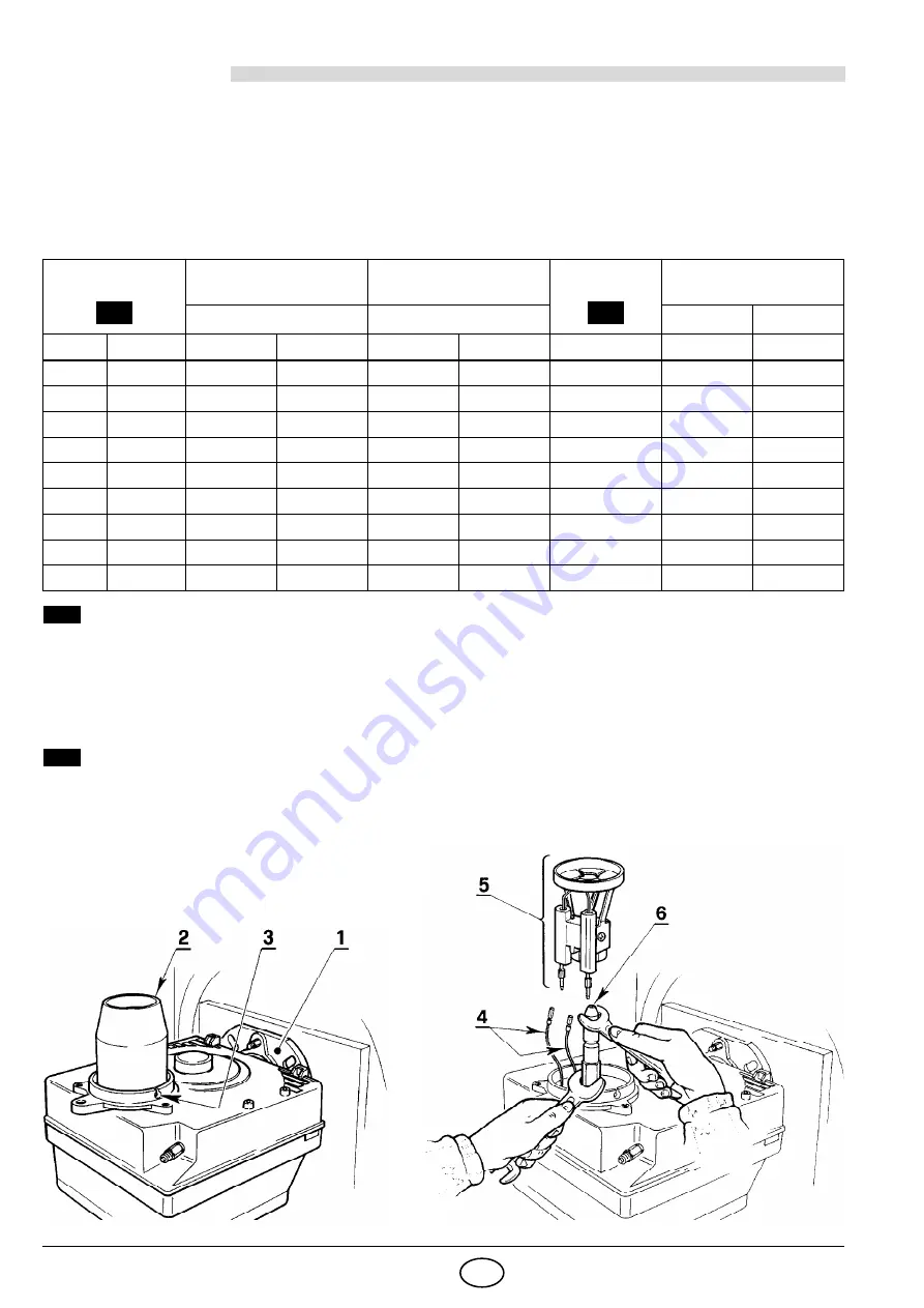
THE ACCESSIBILITY TO THE NOZZLE, THE DIFFUSER DISC AND THE ELECTRODES IS MADE EASY
IN 2 WAYS:


Fig. 11

– Remove the burner out of the boiler, after loosing the fixing nut to the flange.

– Hook the burner to the flange (1), by removing the blast tube (2) after loosing the fixing screws (3).
– Remove the small cables (4) from the electrodes and the diffuser disc-holder assembly (5) from the noz-

zle-holder assembly after loosing its fixing screw (3, fig. 13, page 7).

– Screw the nozzle (6) correctly and tighten 

it as shown in the figure.

A

Содержание 366 T1

Страница 1: ...iks en onderhoudsvoorschriften Montage und Bedienungsanleitung 2902305 5 l Gebl sebrenner Br leur fioul Oil burner Stookoliebrander CODE MODELL MODELE MODEL TYP TYPE 3736650 RG1RKD 366 T1 D F GB NL Zw...

Страница 2: ...Combustion adjustment 6 4 2 Electrodes adjustment 7 4 3 Pump pressure and air output 8 4 4 Fuel heating 9 4 5 Burner start up cycle 9 5 MAINTENANCE 9 6 FAULTS SOLUTIONS 10 1 Pump with pressure reduce...

Страница 3: ...Electrical supply Single phase 230V 10 50Hz Motor Run current 0 85A 2750 rpm 289 rad s Capacitor 4 F Ignition transformer Secondary 8 kV 16 mA Pump Pressure 8 15 bar Absorbed electrical power 0 29 kW...

Страница 4: ...using screws 2 and if necessary the nuts 3 interposing the insulating gasket 5 see fig 2 3 2 FUEL SUPPLY The burner is designed to allow entry of the oil supply pipes on either side Depending on the...

Страница 5: ...over the fuel level a non return valve is required This solution however is less safe than previous one due to the possibility of leakage of the valve 8 H meters L meters i 8 mm i 10 mm 0 5 1 1 5 2 1...

Страница 6: ...sembly of the control box retighten the screw A with a torque wrench setting of 1 1 2 Nm S7186 Fig 10 A 7 pin plug 7 pole socket h L1 B4 S3 T2 T1 N Black White Blue Capacitor Burner earth Switch with...

Страница 7: ...tput Comb head adjustment Air damper adjustment bar kg h 4 1st stage 2nd stage GPH Angle 1st stage 2nd stage 1st stage 2nd stage Set point Set point Set point 0 40 80 9 14 1 3 1 7 0 3 0 0 6 0 50 60 80...

Страница 8: ...ise the setting screw 7 until the set point marked on the regulating rod 8 is level with the outside plane of the nozzle holder assembly 1 In the sketch the combustion head is set for an output of 0 8...

Страница 9: ...pressure gauge must be mounted in place of cap 8 see fig 15 2nd STAGE ADJUSTMENT ADJUSTMENT OF AIR SHUTTER Unloosen the nut 4 turn the screw 5 until the indicator 6 reaches the position desired Then...

Страница 10: ...r control always first switch off the electrical supply to the bur ner acting on the main switch of the system THE BASIC CHECKS ARE Check that there are not obstructions or dents in the supply or retu...

Страница 11: ...of unqualified personnel FAULTS POSSIBLE CAUSES SOLUTION The burner will not start when the ad justment thermo stat closes Lack of electrical supply Check presence of voltage in the L1 N clamps of the...

Отзывы: