


6.
Make sure that the SD card is locked in place.
• To remove the SD card, push it in until it clicks, and release it slowly. The slot pushes out the
SD card.
7.
Turn on the main power switch.
8.
Wait until a firmware name is shown on the display (about 1 minute).
• The firmware name is read from inside the firmware. The firmware name is not changed even
if you change the file name on your PC.
9.
If the necessary firmware name is shown on the display, check the firmware version with
the left-arrow or right-arrow keys. Pressing the left or right-arrow key shows a firmware
name, firmware version and serial number in order.
10.
To use a different firmware, push the up-arrow key or the down-arrow key to find the
necessary firmware.
11.
To select the firmware, push the OK key. Make sure that the selected firmware is high-
lighted.
12.
If you update more than one firmware program at the same time, find each of them and
select each of them. Make sure that the selected firmware is high-lighted.
• If the customer has used all of the slots, you have to keep an empty slot for this procedure. Ask
the customer to temporarily remove the SD card in slot 2.
13.
To start firmware update, push the "UpDate" key. While each firmware is downloaded,
the underscores on the operation panel are replaced by stars.
14.
Wait until the message "Update done" is shown.
15.
Turn off the main power switch.
16.
Remove the SD card from the slot 2.
17.
Attach the slot cover to the SD card slot 2 ( x 1).
18.
Connect the printer to the network physically.
19.
Turn on the main power switch.
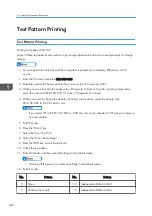
20.
Print the Configuration Page to check that the every firmware is correctly updated: Menu
> List/Test Print > Config. Page
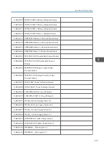
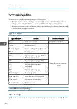
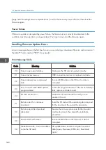
Error Handling
An error code is shown if an error occurs during the download. Error codes have the letter "E" and a
number. If an error occurs, the firmware is not correctly downloaded; see the error code table
Firmware Update
547
Содержание Z-P2
Страница 1: ...Model Z P2 Machine Codes M257 Field Service Manual April 2015 ...
Страница 2: ......
Страница 30: ...1 Product Information 28 ...
Страница 73: ...9 Install the securing holder E 10 Reassemble the machine Tray Heater 71 ...
Страница 85: ...3 Preventive Maintenance Maintenance Tables See Appendices for the following information Maintenance Tables 83 ...
Страница 86: ...3 Preventive Maintenance 84 ...
Страница 92: ...5 Left cover B Right Cover 1 Open the duplex unit A 4 Replacement and Adjustment 90 ...
Страница 94: ...Top Cover 1 Right cover page 90 2 Rear cover page 91 3 Open the upper cover A 4 Replacement and Adjustment 92 ...
Страница 100: ...4 Disconnect the six harnesses A x 1 5 Release the inner right front cover A x 2 4 Replacement and Adjustment 98 ...
Страница 111: ...5 Turn the ITB lock lever clockwise to lock it 6 Use both hands to close the drum securing plate A Image Creation 109 ...
Страница 117: ...17 Release the upper cover sensor A hooks 18 Release the toner plate A x 7 19 Remove each clip A Image Creation 115 ...
Страница 128: ...5 Open the upper cover A 4 Replacement and Adjustment 126 ...
Страница 130: ...2 ITB unit cover A and the handles B 8 hooks 3 Three stays A x 2 each 4 Replacement and Adjustment 128 ...
Страница 131: ...4 The left stay A x 4 5 Rear holder bracket A x 2 Image Transfer 129 ...
Страница 132: ...6 ITB cleaning unit A 7 Pull the tension roller A as shown below 8 Remove a screw 4 Replacement and Adjustment 130 ...
Страница 139: ...3 Remove the two screws 4 ID sensor board bracket A x 1 Image Transfer 137 ...
Страница 141: ...4 Exit the SP mode Image Transfer 139 ...
Страница 143: ...PTR Contact Motor 1 Toner collection motor page 118 2 Interlock switch bracket A x 2 x 4 Paper Transfer 141 ...
Страница 146: ...2 Temperature Humidity sensor A x 1 x 1 4 Replacement and Adjustment 144 ...
Страница 155: ...3 Drum motor CMY A x 3 x 1 Development Motor CMY 1 Right cover page 90 2 Bracket A x 1 Drive Unit 153 ...
Страница 159: ...4 Release the upper harness guide A and the lower harness guide B x 4 x all x all Drive Unit 157 ...
Страница 176: ...12 Right stay A x 3 13 Release the fusing lamp harnesses A x 2 14 Lamp holder A x 1 4 Replacement and Adjustment 174 ...
Страница 177: ...15 Heating roller fusing lamp A Fusing Belt 1 Heating roller fusing lamp page 170 2 C rings and bearings A Fusing 175 ...
Страница 184: ...2 Thermopile base A x 2 x 1 3 Thermopile cover A hooks 4 Thermopile B 4 Replacement and Adjustment 182 ...
Страница 187: ...3 Bracket A x 1 4 Release the paper feed unit A x 1 Paper Feed 185 ...
Страница 189: ...3 Bracket A x 2 4 Registration sensor A x 1 hooks Vertical Transport Sensor 1 Paper feed unit page 184 Paper Feed 187 ...
Страница 195: ...2 Release the harness A x 1 3 Paper feed sensor bracket A x1 4 Paper feed sensor A x1 hooks Paper Feed 193 ...
Страница 198: ...5 Sensor holder A x 3 x 1 6 Disconnect the connector A 7 Tray 1 set sensor A hooks 4 Replacement and Adjustment 196 ...
Страница 201: ...5 Inner left upper cover page 94 6 Paper exit unit holder A x 1 Paper Exit 199 ...
Страница 203: ...3 Remove the bushing C x 1 4 Remove the shaft A and then remove the paper exit upper guide B Paper Exit 201 ...
Страница 211: ...6 Release the left arm A x 1 Duplex Unit 209 ...
Страница 215: ...3 Duplex lower guide plate A 4 Duplex upper guide plate A x 7 Duplex Unit 213 ...
Страница 219: ...5 Fusing fans page 164 6 Operation panel page 93 7 Duplex By pass motor cover A x 1 Duplex Unit 217 ...
Страница 220: ...8 Right and left arms A x 2 each 4 Replacement and Adjustment 218 ...
Страница 221: ...9 Duplex By pass motor bracket with the frame A x 6 10 Guide plate A x 4 Duplex Unit 219 ...
Страница 224: ...3 Guide plate A x 4 4 Slide the roller holder A in the direction of the blue arrow x 2 4 Replacement and Adjustment 222 ...
Страница 225: ...5 By pass feed roller A 6 Slide the roller holder A in the direction of the blue arrow Duplex Unit 223 ...
Страница 229: ...Electrical Components Boards Rear Cover Open A Bridge Board B Controller Board C PSU Electrical Components 227 ...
Страница 230: ...Controller Box Removal E HVPS CB Board Right Cover Open F BCU 4 Replacement and Adjustment 228 ...
Страница 239: ...6 Remove the screw and disconnect the connector 7 Remove the seven screws Electrical Components 237 ...
Страница 245: ...5 Disconnect the connector 6 Disconnect the six connectors x 1 Electrical Components 243 ...
Страница 254: ...4 Replacement and Adjustment 252 ...
Страница 421: ...Engine SP Mode Tables SP4000 There are no Group 4 SP modes for this machine Engine SP Mode Tables SP4000 419 ...
Страница 473: ...5 992 025 SDK J Application Info CTL Execute 5 992 026 Printer SP mode CTL Execute Engine SP Mode Tables SP5000 471 ...
Страница 474: ...Engine SP Mode Tables SP6000 There are no Group 6 SP modes for this machine 5 System Maintenance Reference 472 ...
Страница 564: ...5 System Maintenance Reference 562 ...
Страница 637: ...Model Z P2 Machine Codes M257 Appendices February 2015 ...
Страница 638: ......
Страница 640: ...2 ...
Страница 648: ...1 Appendix Specifications 10 ...
Страница 652: ...MEMO 14 ...
Страница 653: ...MEMO 15 ...
Страница 654: ...MEMO 16 EN ...