3-46
Confidential
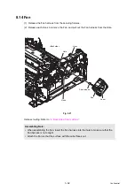
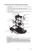
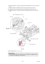
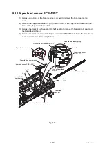
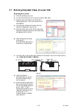
(2) Release the Hook A, and remove the Eject sensor PCB ASSY from the Pin of the Frame L
unit.
(3) Release the Back cover/duplex tray sensor harness from the securing fixtures.
(4) Release the Hook B, and remove the DX sensor stopper 2 from the Frame L unit.
(5) Release each Hook C, and remove the Back cover/duplex tray sensor from the Frame L
unit.
Fig. 3-45
Harness routing: Refer to
.
Assembling Note:
• When assembling the Back cover/duplex tray sensor, attach it by engaging the Hooks
C of the Back cover/duplex tray sensor properly.
Pin
Back cover/duplex
tray sensor
Frame L unit
Hook A
Back cover/duplex tray sensor
Eject sensor PCB ASSY
Back cover/duplex tray sensor harness
Hook B
DX sensor stopper 2
Hooks C

