20
Connection
Before connection
Read the owner’s manual of the device you are connecting to the projector.
Some computers cannot be used with or connected to this projector.
Check for an RGB output terminal, supported signal, etc.
Turn off the power of both devices before connecting.
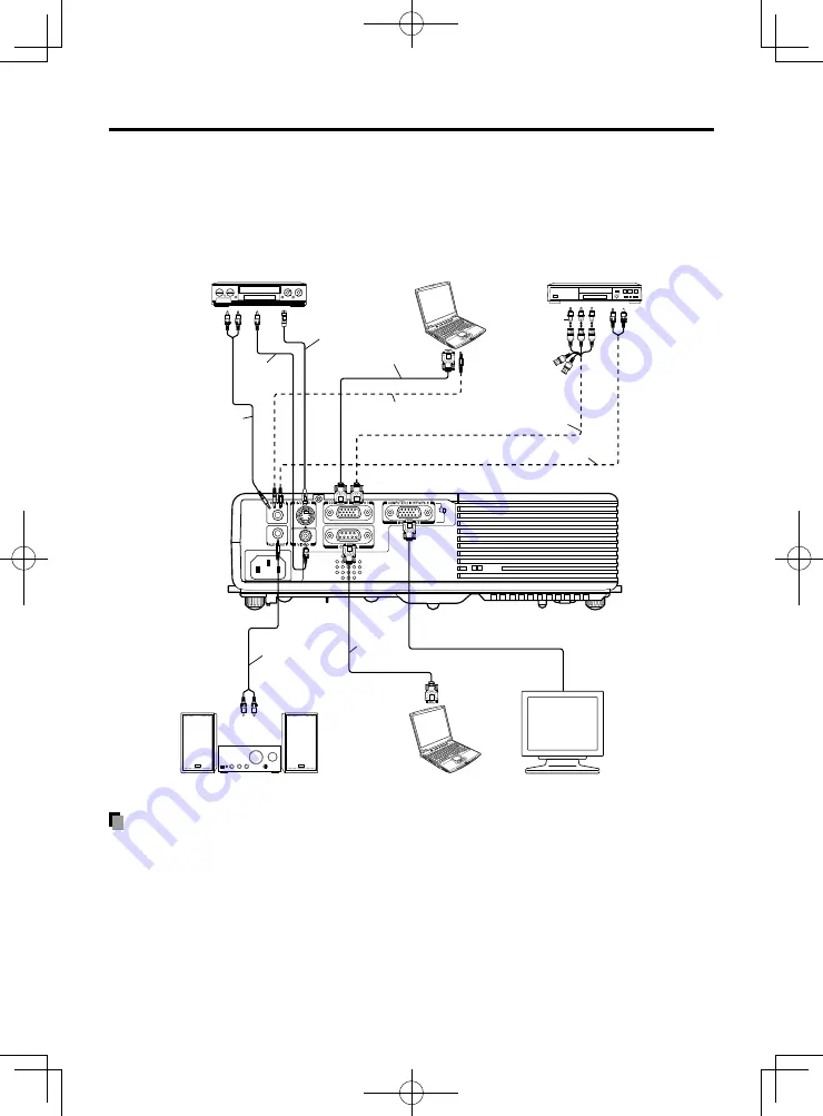
The figure below shows sample connections. This does not mean that all of these devices
can or must be connected simultaneously. (Dotted lines mean items can be exchanged.)
Notes
When COMPUTER 2 IN terminal is used as MONITOR OUT terminal, the signal which is
input to COMPUTER 1 IN terminal is output.
Signals are output from MONITOR OUT terminal even in standby mode.
However, from AUDIO OUT terminal, no audio signal is output.
A computer monitor cannot accept Y/P
B
/P
R
signals correctly.
The AUDIO IN terminal can be used for devices connected to COMPUTER 1 terminal,
COMPUTER 2 terminal, VIDEO terminal and S-VIDEO terminal.
When an AUDIO OUT terminal is connected, sound is not output from the projector speaker.
Output volume of AUDIO OUT terminal can be adjusted by the
VOL
button.
•
•
•
•
•
•
•
•
•
•
To audio
output
Audio cable (not supplied)
Conversion adapter
BNC-pin (not supplied)
To Y/C
B
/CR output
Green(Y)/Blue(C
B
)/
Red (C
R
)
RGB cable
(supplied)
Video cable
(not supplied)
Audio cable
(not supplied)
To audio
output
White (L)/
Red (R)
To RS-232C
terminal
Audio cable
(not supplied)
Video recorder,
DVD player, etc.
Computer
To
video
output
DVD video recorder, etc.
Audio cable
(not supplied)
Monitor cable Mini
D-sub 15P-BNC
(not supplied)
To audio
output
White (L)/
Red (R)
To RGB output
Computer (for control)
To
S-video
output
To audio input
White (L)/Red ( R)
Audio amplifier, etc.
It is necessary to
switch to MONITOR
OUT by the switch.
S-video cable
(not supplied)
Control
cable (not
supplied)
* The connection for COMPUTER 1 IN terminal described here is also applicable for COMPUTER 2 IN terminal.
Monitor
PJ2a̲d̲c̲Getting̲F-EN.indb 20
PJ2a̲d̲c̲Getting̲F-EN.indb 20
2011/1/12 14:22:55
2011/1/12 14:22:55


