Ricoh Mo-C1 Скачать руководство пользователя страница 571

3. Remove the SD slot cover [1] ( x1).
4. Insert the SD card [2] with the firmware in SD card Slot 2. (If there is an SD card in Slot 2, remove

it.)

5. Turn on the main power switch. "Program to start firmware update" appears on the operation panel

display.

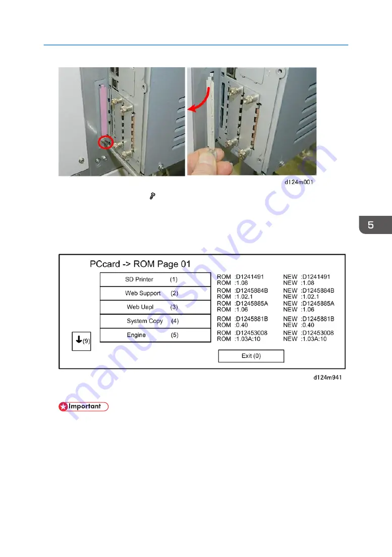
After approximately 90 sec. the initial firmware update screen appears.

• Only the firmware update applications on the SD card are displayed in the menu. If more than

one update is to be done, the System Copy and Engine updates should always be done first.

6. Look at the numbers in the right (ROM) and left (NEW) columns.

• If the NEW number is higher than the ROM number the application needs to be updated.
• If the numbers are the same, the application does not need to be updated.

7. Press the down arrow to see the next screen.

System Maintenance Tasks

569

Содержание Mo-C1

Страница 1: ...Model Mo C1 Machine Code D124 Field Service Manual November 2012...

Страница 2: ......

Страница 3: ...rt B Class B Switches and Symbols Where symbols are used on or near switches on machines for Europe and other areas the meaning of each symbol conforms with IEC60417 Responsibilities of the Customer E...

Страница 4: ...ver wear loose fitting clothing or accessories neckties loose sweaters bracelets etc or casual footwear slippers sandals etc when lifting or moving the machine Always unplug the power cord from the po...

Страница 5: ...ncorrectly or using tools that could damage parts could damage the machine or cause injuries During Maintenance General Before you begin a maintenance procedure always switch the machine off Disconnec...

Страница 6: ...d cause a fire or other problems Always check the power plug and make sure that it is free of dust and lint Clean it if necessary A dirty plug can generate heat and cause a fire Inspect the entire len...

Страница 7: ...operating instructions Point out the parts inside the machine that they should not touch or attempt to remove Confirm that operators know how to store and dispose of consumables such as ink cartridge...

Страница 8: ...idges out of the reach of children Always store ink cartridges in a cool dry location that is not exposed to direct sunlight Ink Cartridge Disposal Attach the caps to empty ink containers for temporar...

Страница 9: ...s regarding the disposal of such items Conventions Symbol What it means Bushing C ring Connector E ring FFC Flexible Film Cable Gear Harness clamp Hex head screw Hook or tab release Knob screw black K...

Страница 10: ...hazardous situation Failure to obey a Warning could result in death or serious injury A Caution indicates a potentially hazardous situation Failure to obey a Caution could result in minor or moderate...

Страница 11: ...any Ethernet is a registered trademark of Xerox Corporation PowerPC is a registered trademark of International Business Machines Corporation Other product names used herein are for identification purp...

Страница 12: ...Features Model Numbers and Names Model Number Name D124 17 Ricoh MP CW2200 SP Gestetner MP CW2200 Savin MP CW2200 Lanier MP CW2200 D124 21 Ricoh MP CW2200 SP D124 27 Ricoh MP CW2200 SP NRG MP CW2200 S...

Страница 13: ...d Peripherals No Item Machine Code Main Machine and Stand D124 Scanning Unit and Stand Standard Roll Unit Standard Exit Stacker Standard Roll Unit RU6520 D622 01 Option Other Options Option No Slot Br...

Страница 14: ...ace Unit Type J D377 02 Board B EU IEEE 802 11 g Interface Unit Type K D377 19 Board B Other Main Features Comparison with Other Earlier Printers Horizontal carriage movement during printing A horizon...

Страница 15: ...roller 4 to feed paper in the paper path The diameter of the exit roller is slightly larger than the diameter of the registration roller This keeps the paper slightly stretched to prevent buckling The...

Страница 16: ...or 1 raises the suction cap 2 that cleans the print heads and caps the K1 print head raises the wiper blade 3 moves the wiper 4 and drives the suction pump 5 The maintenance lift motor 6 raises the th...

Страница 17: ...the right side of the machine Ink pumps 2 pump ink through ink supply tubes 3 to the ink sub tanks 4 mounted above each print head Each ink cartridge has an ID chip These chips keep an accurate count...

Страница 18: ...signal when the tank is full and needs to be replaced A right ink sump 3 mounted behind the waste ink collector catches waste ink that is scraped from the surfaces of the heads during print head clean...

Страница 19: ...d for servicing or for placing the scanner on a low table or desk so it can be operated from a sitting position Image registration The DRESS Direct Realization Edge Scanning Sensor sensor mounted on t...

Страница 20: ...are set in tracks which guide the cover into the correct closed position The front cover track switch 4 a push switch has been added to ensure that these guide pins are inserted correctly into the lef...

Страница 21: ...he machine after cutting It moves below the paper without interfering with paper feed Paper feed control The DSP control Digital Signal Processing system controls paper feed with encoder wheels It ass...

Страница 22: ...one pass in a monochrome print During color printing B the K2 3 C 4 and YM 5 print heads are used The band is narrower because the forward sitting K1 print head is not used The K1 print head H1 sits f...

Страница 23: ...arrangement of the nozzle ports is staggered so the positions of the nozzle ports complement one another when ink is put down on the paper 21...

Страница 24: ...0 Main Machine Peripherals Options 11 Main Features 12 1 Product Information Specifications 31 Main Machine Peripherals Options 32 Guidance for Those Who Are Familiar with Predecessor Products 34 Comp...

Страница 25: ...5 Ink Collector Tank Storage Shelf 107 Assemble and Install the Exit Stacker 108 Ink Filling 120 Set Roll Paper 123 Rewinding a Roll 128 Check Printing 129 Final Adjustments 132 Final Settings 142 Aft...

Страница 26: ...cautions 196 Common Procedures 201 Before You Begin 201 Before Servicing the Machine 202 Separate the Main Unit from the Scanner Unit 205 Ink Collector Tank 207 Paper Rolls 207 Main Covers 208 Front C...

Страница 27: ...nit Left Covers 308 Paper Release Sensor 310 Separate the Roller Housing 312 Entrance Sensor Exit Sensor 321 Roll Feed Roller 323 Roll Feed Motor 327 Encoder Sensors 328 Roll Feed Clutch 330 Roll End...

Страница 28: ...int Heads 381 DRESS Sensor 415 Main Ink Level Sensors 419 Horizontal Encoder Sensor 423 Head Lift Motor 426 Carriage Unit 427 Ink Supply 453 Air Release Solenoid 453 Temperature Humidity Sensor 457 In...

Страница 29: ...l Adjust Head Position 538 Adjust Paper Feed 542 Adjust Print Position 544 Special Adjustments 547 Image Adjustment with SP Modes 547 CIS Adjustment with SP Modes 555 5 System Maintenance Reference Se...

Страница 30: ...tware 642 Printing Problems 648 Before You Begin 648 White Lines Horizontal Banding 648 Horizontal Lines In Margins 649 White Color Vertical Banding 650 Overall Poor Image Quality 650 Text Shifted Out...

Страница 31: ...Units 674 Ink Supply 675 Carriage Unit 677 Around the Carriage Unit 679 Maintenance Unit 680 Boards 682 Fuses 684 Scanner Unit 684 Main Boards Rear Box 685 Carriage Unit 692 7 Energy and Paper Saving...

Страница 32: ...30...

Страница 33: ...1 Product Information Specifications See Appendices for the following information General Specifications Printer Specifications Scanning Specifications Option Specifications 31...

Страница 34: ...ls No Item Machine Code Main Machine and Stand D124 Scanning Unit and Stand Standard Roll Unit Standard Exit Stacker Standard Roll Unit RU6520 D622 01 Option Other Options Option No Slot Browser Unit...

Страница 35: ...SD Card Slot 1 or 2 File Format Converter Type M5 D625 Board A Gigabit Ethernet Type B D377 21 Board C IEEE 802 11 a g Interface Unit Type J D377 01 Board B NA IEEE 802 11 a g Interface Unit Type J D...

Страница 36: ...anning Yes Yes Controller GW GW Copying printing Inkjet Technology Electrostatic photo HDD overwrite encryption Yes Std Yes Std Languages 20 Languages 18 Languages Media to print Yes Std No Memory Sta...

Страница 37: ...AP C2 supports this new technology and enables users to enjoy the following benefits Automatic driver installation of network printer To discover an available printer without inputting an IP address a...

Страница 38: ...Sensor There are five of these sensors one for each color mounted on the carriage unit A feeler arm attached to the flexible side of each color tank swings in and out of the sensor gap as the ink sup...

Страница 39: ...he Machine Front 1 Original Stacker 6 Front Cover 2 Operation Panel 7 Paper Exit Guide 3 USB Cable 8 Paper Holding Lever 4 Scanner Unit Cover 9 Ink Cartridge Cover 5 Original Table 10 Exit Stacker Ove...

Страница 40: ...guide 1 guides it to the original stacker 2 on top of the machine 2 Operation Panel This machine features a full operation panel 1 Function Keys 2 Color LCD featuring an 8 4 in WVGA and touch panel 3...

Страница 41: ...D 3 USB Cable A USB cable 1 is permanently attached to the back of the operation panel The end of this USB cable is plugged into the USB Host slot of the machine controller on the back of the machine...

Страница 42: ...le of the scanner unit can be adjusted to accept originals up to 914 4 mm 36 in for scanning Original length is limited to 15 m 49 ft 6 Front Cover The front cover is easily raised and lowered to expo...

Страница 43: ...open switch signals a cover open error if the front cover is down but not correctly set in the track 7 Paper Exit Guide The paper exit guide guides printed paper from the machine into the exit stacker...

Страница 44: ...revents the guide from falling abruptly 8 Paper Holding Lever There is no bypass feed tray but paper can be fed manually for bypass printing Raising the paper holding lever 1 lifts the registration ro...

Страница 45: ...ached to the front of the machine can be adjusted for output 1 Basket mode and 2 Stack mode Basket Mode For standard size paper The exit stacker is shortened so that it is rounded and deep to hold pap...

Страница 46: ...Ink Collector Tank Cover 5 Ink Collector Tank The optical cloth holder 1 attached to the right side of the scanner unit holds the accessory optical cloth 2 which can be used to clean the exposure glas...

Страница 47: ...ord 2 Power Switch 3 Manual Pocket The power cord 1 power switch 2 and manual pocket 3 are on the left side of the machine There is only one power switch on this machine that can cycle the machine off...

Страница 48: ...ine to hold originals that exit the back of the machine The PCB box cover 2 covers the area where the controller board and all other PCBs are mounted on the back of the machine Four braided ground har...

Страница 49: ...Main Sections The machine is comprised of five main sections A Scanner Five staggered CIS units above the original path scan images from the original Overview 47...

Страница 50: ...that can hold 6 cc of ink There are two K print heads and one head each for Y M and C The print heads can be replaced on site Main scan unit Refers to the horizontal motor and horizontal encoder that...

Страница 51: ...r E Exit Stacker A cloth frame stacker that holds prints as they are output from the machine The stacker can hold many different sizes of paper Capacity 10 sheets The printed sheets are stored in the...

Страница 52: ...ion panel 2 Scanner unit 3 Scanner stand 4 Main unit stand 5 Carriage unit 6 Air release solenoid 7 Maintenance unit 8 Ink supply unit 9 Roll Unit 1 Std 10 Roll Unit 2 Option 11 Exit stacker 1 Product...

Страница 53: ...Drive Layout No Item 1 Scanner motor 2 Horizontal motor 3 Vertical motor 4 Maintenance motor 5 Maintenance lift motor 6 Roll paper feed motor 1 7 Roll paper feed motor 2 Overview 51...

Страница 54: ...No Item 8 Ink pump motors five 9 Cutter motor 10 Air release solenoid 11 Head lift motor 1 Product Information 52...

Страница 55: ...Original Path Paper Paths No Item A Original path 1 Original width sensors 2 Original set sensor Overview 53...

Страница 56: ...ance sensor Roll Unit 2 9 Exit sensor Roll Unit 2 10 Roll end sensor Roll Unit 1 11 Entrance sensor Roll Unit 1 12 Exit sensor Roll Unit 1 13 Pre registration sensor 14 DRESS sensor 15 Exit sensor C B...

Страница 57: ...ne is exposed to direct sunlight this could cause vertical black and white lines in scanned images If the machine is near a window turn it around so the back of the machine is not facing the window an...

Страница 58: ...rea can cause poor reproduction of filled areas in images 8 Do not install the machine in areas higher than 2 000 m 6 600 ft above sea level 9 Put the machine on a strong and level surface The floor o...

Страница 59: ...damage to the breaker switch installation of a voltage stabilizer constant voltage transformer is recommended for work sites where there is fluctuation in the AC power source To protect the HDD always...

Страница 60: ...ct Host USB Cable Connect and Clamp Power Cord Clamp Main Harness 9 Remove Tapes and Shipping Materials 10 Original Stacker Guides 11 Ink Collector Tank Storage Shelf 12 Assemble and Install Exit Stac...

Страница 61: ...nt 2 Main Unit 3 Accessories 4 Roll Unit 1 Roll Paper Spool x2 Transport Guide 5 Scanner Stand Main Unit Stand Hex bolts for Stands Allen Key The screws for each unit are packed together with the unit...

Страница 62: ...One is provided but you may need extra keys if two or more people are working on the installation Driver 300 cm 12 in or longer Flashlight Small scale or ruler Adjustable wrench To avoid serious injur...

Страница 63: ...tay 2 4 Hex Socket Bolt M4x8 1 with lock washers 20 5 Clamp 3 1 For the scanner stand assembly and connection of scanner stand to main unit with these bolts you will need an Allen key Items 4 and 5 ar...

Страница 64: ...stallation Scanner Stand Be sure to attach one lock washer to each hex socket bolt before you fasten the bolt 1 Position the left and right supports of the scanner stand as shown above 2 Installation...

Страница 65: ...he ends of the stays on the ends of both stays 5 Insert and finger tighten the end of each stay to the left and right supports x16 Do not tighten the hex head bolts until all have been inserted 6 Afte...

Страница 66: ...7 Set the assembled stand upright This completes assembly of the scanner stand Assemble the Main Unit Stand Accessories Main Stand 2 Installation 64...

Страница 67: ...ex Socket Bolt 2 with lock washers 10 12 Screw 4 13 Screw 10 14 Screw 9 15 Screw 1 16 Screw 6 17 Power Cord 1 18 Original Stacker 1 19 Original Guide 2 20 Manual Pocket 1 21 Optical Cloth Pocket 1 22...

Страница 68: ...Main Stand Be sure to attach one lock washer to each hex socket bolt before you fasten the bolt 1 While supporting the right support with your hand latch a stay to the rear base of the support 2 Inst...

Страница 69: ...e base of the left support so the supports can stand upright by themselves 3 Latch the other stay to the base of the left and right support at the front 4 Push down the front and rear stays to lock th...

Страница 70: ...from the pallet and open the box 1 Locate the vertical positioning pins on top of both sides of the assembled scanner stand 2 Remove the orange tape from both ends of the scanner unit 3 Arrange the ha...

Страница 71: ...s in the frame of the scanner unit with the positioning pins on either end of the scanner stand 6 Set the scanner unit down on the positioning pins then fasten the unit to the stand x4 M4x8 Main Machi...

Страница 72: ...Make a copy of the Factory Settings Sheet and leave the original with the machine for future reference Mount the Main Unit Mount the main unit immediately after you remove it from the pallet and open...

Страница 73: ...1 Locate the vertical positioning pins on the tops of both sides of the main unit stand 2 Locate the handles on the right side of the main unit Main Machine Installation 71...

Страница 74: ...es on the left side of the main unit 4 With two people holding the left end A and right end B with their hands positioned as shown above lift the main unit and hold it over the top the main unit stand...

Страница 75: ...so that the triangle marks at the rear are aligned 6 With the marks aligned lower the main unit so that the positioning pins on either end of the stand insert smoothly into the holes in the bottom of...

Страница 76: ...lock washer 8 Under the stand use an Allen key to fasten the left and right sides of the stand to the bottom of the main unit with the hex head bolts and lock washers x3 M4x8 Confirm that each bolt is...

Страница 77: ...ty 1 Paper Transport Guide Plate Semi Transparent 1 2 Roll Unit 1 1 3 Roll Spool with Stoppers 1 4 Screw M3x8 with Spring Washer for Roll Unit 4 5 Screw M3x6 for Paper Transport Guide 2 6 Screw for Ha...

Страница 78: ...Installation Roll Unit 1 1 Raise the paper exit guide A 2 Locate the positioning pins on the left and right ends of the roll feed unit 2 Installation 76...

Страница 79: ...uts in the left and right supports of the main unit stand 4 Lay the harness away from the back of the roll feed unit as shown above so that the harness will not interfere with installation Main Machin...

Страница 80: ...nit in place 6 Behind the stand on both sides make sure that the holes of the roll feed unit and the stand frame are aligned 7 Insert the tip of a long screwdriver 30 cm 12 in through each pair of hol...

Страница 81: ...holding the paper transport guide with both hands as shown above insert the pegs on either end of the guide into the cut outs in the stand on the left A and right B The guide should slide into positi...

Страница 82: ...en the guide to the frame on the right C and left D x2 14 Use a thin edge like the end of a metal scale to push the tongues of the guide mylar up and behind the plate There are six mylar tongues Paper...

Страница 83: ...the harness and then close the clamps x3 16 Remove the screws marked by red arrows x6 17 Loosen do not remove the screws marked by the blue arrows x10 18 Slide the cover to the right and remove it Ma...

Страница 84: ...the machine locate the knockout A on the bottom edge of the electrical component box 20 Attach the harness bracket B x2 21 Route the harness connect it to the MCU at A CN215 and then clamp it x4 x1 2...

Страница 85: ...tor B is for Roll Unit 2 23 If you intend to install Roll Unit 2 option go to the next section or If you are finished re attach the rear cover Roll Unit 2 D622 Option One additional roll unit can be i...

Страница 86: ...ll Spool with Stoppers 1 3 Paper Transport Guide Plate 1 4 Clamp 3 5 Screw M3x6 for Paper Transport Guide 2 6 Screw M3x8 with Spring Washer for Roll Unit 4 7 Screw for Harness Bracket 2 8 Screw for RF...

Страница 87: ...Installation 1 Unpack the roll feed unit Locate the positioning pins on the left and right ends 2 Locate the cut outs in the left and right supports of the main unit stand Main Machine Installation 85...

Страница 88: ...rness will not interfere with installation 4 While holding the unit with both hands Set the positioning pins on the left and right end of the roll feed unit into the cut outs in the supports Push the...

Страница 89: ...of holes to make sure that they are aligned 6 Fasten the roll feed unit to the stand x4 M3x8 Be sure to use the screws with the washers attached 7 Attach the three harness clamps and then close the cl...

Страница 90: ...x2 x2 9 The cut out for the harness bracket is covered by a plate B 10 Under the edge of the box C unfasten the plate and discard it x2 11 Fasten the harness bracket to the bottom of the box x2 12 Ope...

Страница 91: ...ted above at CN910 of the MCU above x1 14 Connect the harness 1 at CN301 x1 15 Connect one end of the accessory harness 2 to the RFDB at CN300 x1 16 Connect the other end of the accessory harness 3 to...

Страница 92: ...17 Open the ferrite core lay the harnesses into the center of the core and then close the core 18 Close the clamps x3 2 Installation 90...

Страница 93: ...ift the guide slightly and then insert the bottom pegs into the cut outs at the lower left and lower right corners 21 Check each corner of the plate to be sure that each peg is snug in its cut out 22...

Страница 94: ...with paper in the bypass feed path During bypass feed the trailing edge of the paper will come out from the back of the machine and then reverse feed back into the machine Controller Options If you i...

Страница 95: ...nit close together as shown above The scanner unit is top heavy and unstable It can fall over easily Grip the supports below the scanner unit and push it slowly when you move it 2 Make sure that the h...

Страница 96: ...hed between the stand and back of the machine when the scanner stand is docked to the back of the machine 3 Set the scanner cable bracket in the cutout in the bottom edge of the PCB box 4 Fasten the b...

Страница 97: ...Connect the relay harness B x1 7 Insert the 6 pin connector of the harness into A at CN125 on the PSU 8 Insert the 19 pin connector of the harness into B at CN201 on the MCU 9 Close the harness clamps...

Страница 98: ...ch ground wire B x1 12 Starting at the I F cable bracket A route and clamp the white and black harness from right to left x6 13 Insert the connector of the scanner cable at A at CN251 on the IPU x1 14...

Страница 99: ...ed cable with the clamp and screw x1 16 Route the black ground wire through the clamp A x1 17 On the other side of the partition fasten ground wire B x1 M3x6 18 After completing the harness and wire c...

Страница 100: ...the back Make sure all the attached screws are snug in their cut outs Re attach the removed screws marked by the red arrows x6 Tighten the screws marked by the blue arrows x10 Connect the Host USB Ca...

Страница 101: ...e machine 2 Push the scanner stand close to the main unit stand 3 At the back of the operation panel set the cable in the groove 4 Remove the tape from the back of Velcro clamps and then set them at p...

Страница 102: ...as much slack as possible Connect and Clamp the Power Cord Clamp the Main Harness 1 Make sure that the power switch is OFF 2 Confirm that the power cord is not connected to the power source 3 Attach t...

Страница 103: ...m until the tops are flat with the top of the stand feet but the bottoms do not touch the floor This prevents the bolts from interfering with the docking of the scanner stand and the installation of t...

Страница 104: ...left A x2 5 Fasten the scanner stand to the main unit bracket on the right B x2 6 Connect the USB cable from the operation panel to the controller box x1 Connect Ground Harnesses 1 Connect the ground...

Страница 105: ...e scanner unit and remove the paper sheet 2 Remove all the external tape and other materials attached to the machine 3 Lift the front cover and then fold the bottom into the machine so that it locks a...

Страница 106: ...4 Remove the tape and cardboard 5 Close the front cover Push it in and make sure that it locks 2 Installation 104 RTB 26 This step was modified...

Страница 107: ...tacker Guides 1 Insert the projections on the bottoms of the original stacker A into the holes 2 Push down the four tabs B to attach 3 Attach the original guides behind the stacker Main Machine Instal...

Страница 108: ...the guides However attach the guides to the inner four points leave both outer slots empty 5 Use the rivets to attach the manual pocket to the left side of the main unit stand x2 To set a rivet align...

Страница 109: ...the surface where the optical cloth pocket will be attached Remove the tape from the back of the pocket and then attach it as shown above 7 Place the optical cloth in the pocket Ink Collector Tank St...

Страница 110: ...tank becomes full the machine will stop The operator can remove the full tank and replace it with the empty tank At the next PM visit the service technician can swap the full tank with another empty t...

Страница 111: ...t 2 6 Wire Guide 2 7 Plate Bracket Small 1 8 Plate Bracket Large 1 9 Side Frame 2 10 Hex Socket Bolt M4x8 1 10 1 You will need an Allen key to attach the hex socket bolts Installation Exit Stacker 1 I...

Страница 112: ...ight foot use an Allen key to Attach molded bracket A x1 Attach large plate bracket B x1 3 On the left foot use an Allen key to Attach one molded bracket A x1 Attach small plate bracket B x1 2 Install...

Страница 113: ...left side frame the one with the number decals on the plate bracket of the left foot 5 Fasten the left side arm to the left foot x2 6 Fasten the right side arm to the right foot x1 Main Machine Instal...

Страница 114: ...right foot set the shaft as shown at A not B 8 On the left foot set the shaft as shown at A not B 9 Turn the cloth with the rod sleeve A facing down and then spread the cloth on the floor 2 Installat...

Страница 115: ...ert the remaining short rods through the other sleeves The rear rod is marked with an exclamation mark The center rod above is unmarked It is the same length as the rod marked with the exclamation mar...

Страница 116: ...on the left and right side of the frame 15 Set both ends of the long cap less rod marked at the front edge of the cloth into the L brackets on the ends of the left and right arms When you set the ends...

Страница 117: ...eves 17 At the front pass the long rod marked into the left slit A through the center slit B and out of the right slit C 18 Set the end of the rod A marked with the 2 decal on the left in front of the...

Страница 118: ...in its L joints Check both ends of the front rod and make sure that the ends of the rod are inserted tightly into the L joints 20 Insert the end of the rod marked into the round hole of the right side...

Страница 119: ...cloth 24 Push the end of the rod through the hole in the arm on the left B 25 This completes the installation of the exit stacker Changing Exit Stacker Mode The configuration of the exit stacker can...

Страница 120: ...A0 A1 SEF paper The exit stacker is shortened so that it is rounded and deep to hold paper in a small well Holds one sheet 1 In the photo on the left the extension A is down and the rod B is at the r...

Страница 121: ...s of the extension A Wire Guide Mode For A1 SEF A2 LEF Paper With the exit stacker set up for either the basket mode or stacker mode two wire guides can be attached for A1 SEF or A2 LEF paper Main Mac...

Страница 122: ...nd print heads are filled with fluid This priming fluid prevents the seams of the joints and connections of the ink supply system from drying out during shipping and storage The priming fluid must be...

Страница 123: ...nel during the following procedure Do not touch the machine while it is draining Draining and Filling Procedure 1 Remove the drain cartridges 1 and starter ink cartridges 2 from their packing material...

Страница 124: ...s not start go to the next section below for more about an alternative procedure 10 Turn the machine off 11 Remove the primer fluid drain cartridges and replace them with the starter ink cartridges 12...

Страница 125: ...the ink cartridge cover 5 Turn the machine on Ink filling starts The ink and primer fluid are purged from the tubes ink sub tanks and the print heads into the ink collector tank 6 After the operation...

Страница 126: ...4 Raise the paper exit guide 5 Remove the exit stacker rod attached to the front of Roll Unit 1 6 Lower the exit stacker rod attached to the front of Roll Unit 2 if it is installed 2 Installation 124...

Страница 127: ...oll core Both roller stoppers must be set identically For a 2 in core lower the levers 1 of both stoppers so they are flat For a 3 in core raise the levers 2 of both stoppers 8 Set the roll on the sha...

Страница 128: ...with your hand on the right end of the paper roll press the left paper holder with your other hand until the right end of the roll is against the right paper holder Lower and lock the lever of the le...

Страница 129: ...of the paper passes over the top of the paper guide inside the machine 15 Insert the leading edge of the roll paper below the roller at the feed slot and then feed the paper into the machine until th...

Страница 130: ...Paper Type and Paper Thickness Settings match those of the paper loaded in the machine or Touch Does Not Match if the Paper Type and Paper Thickness Settings do not match those of the paper loaded in...

Страница 131: ...ine has remained idle for a long time before you use the machine it is recommended that your rewind the roll cut off the equivalent of two full roll rotations and then reload the paper Check Printing...

Страница 132: ...inting touch Exit and then flush the print heads Flushing the print heads consumes a large amount of ink Never execute print head flushing until you have executed print head cleaning at least 3 times...

Страница 133: ...n SP2100 002 Enter the number of the print head that is abnormal To Service Color You Enter Head 1 K1 Black 1 Head 2 K2 Black 2 Head 3 C Cyan 4 Head 4 YM Yellow Magenta 8 All K C Y M 15 If you need to...

Страница 134: ...If you detect any streaking flush the print head of the color where you see the problem Press User Tools on the operation panel Touch Maintenance Flush Print heads When the message tells you flushing...

Страница 135: ...is on an uneven surface 1 Place a shoe under the bolt at each corner of the machine 2 Turn each bolt to lower it onto the shoe until it is snug 3 Open the front cover 4 Place a level on the cross piec...

Страница 136: ...the machine Front to back Not more than 5 mm from level Right to left Not more than 0 15 1000 mm from level Manual Adjust Head Position 1 Press the button on the operation panel 2 Touch Maintenance 3...

Страница 137: ...Roll Unit 1 Paper Input Location 2 Roll Unit 2 Resolution Speed Draft Standard Standard quality Quality High quality 4 Select the Target Location and Resolution and then touch Start Printing A message...

Страница 138: ...he square is the adjustment value If you still cannot determine the adjustment value select the square that is between the straightest vertical lines Write down these values for use later in the proce...

Страница 139: ...new test pattern Adjust Paper Feed Adjust paper feed if you see these problems in the prints Broken horizontal lines Patchy images uneven filled areas White lines at regular intervals 1 Press the but...

Страница 140: ...tern for the paper feed source Paper Bypass Location Bypass paper feed Paper Input Location 1 Roll Unit 1 Paper Input Location 2 Roll Unit 2 5 When you are prompted to start the print touch Start Prin...

Страница 141: ...6 The adjustment value appears to the left of the lightest gray square with straight horizontal lines on both sides 7 Touch Adjustment Main Machine Installation 139...

Страница 142: ...essing either key increments decrements the numbers automatically Adjust Print Position This procedure checks and allows you to adjust the print start position at the upper left corner of each sheet 1...

Страница 143: ...aper Input Location 2 Roll Unit 2 5 When you are prompted to start the print touch Start Printing A message will ask you to wait while the test sheet is printing 6 The black arrow indicates the direct...

Страница 144: ...After Installation Do these tasks after installation is completed 1 Make a copy of the Factory Settings Sheet and store the original with the machine 2 Upload the NVRAM contents to an SD card Insert...

Страница 145: ...er stand are unlocked before you try to move the machine It is not necessary to remove the ink cartridges Position your hands at base of the main unit and then push it slowly to the new location Befor...

Страница 146: ...D cards are written on a decal on the controller box cover as shown below Always touch a grounded surface to discharge static electricity from your hands before you handle SD cards printed circuit boa...

Страница 147: ...re the machine leaves the factory Controller Options The controller options available for this machine are listed in the table below Option No Slot Browser Unit Type M5 D624 02 SD Slot 1 or 2 Data Ove...

Страница 148: ...Converter MLB Accessories No Item Q ty 1 Mother Board 1 2 File Format Converter 1 3 Standoff 1 4 Screw 1 Installation Preparation Separate the main unit from the scanner unit Remove Rear cover 2 Insta...

Страница 149: ...1 Disconnect the mother board and HDD from the controller board x1 x6 One connector A is empty No harness is connected here 2 Remove the SD card slot cover x1 Controller Options 147...

Страница 150: ...3 Remove the controller box faceplate x2 4 Disconnect the mother board bracket x3 x1 2 Installation 148...

Страница 151: ...5 Slide the controller board and mother board out of the machine 6 Disconnect the mother board from the controller board Controller Options 149...

Страница 152: ...7 Disconnect the mother board from its bracket x2 Keep these screws 8 Fasten the standoff to the bottom of the bracket x1 2 Installation 150...

Страница 153: ...ther board to the bracket x3 10 Fasten and tighten the screws in the order 1 2 3 11 Connect the mother board 1 to the back of the controller board 12 Slide the controller board 2 into the machine Cont...

Страница 154: ...13 Reattach the controller board faceplate x2 14 Reattach the mother board bracket at A x3 x1 15 Remove the cover of Slot A B x2 2 Installation 152...

Страница 155: ...the board connects completely at B 18 Tighten the knob screws C with your fingers x2 To avoid twisting and damaging the boards finger tighten the knob screws Do not use a screwdriver 19 Reconnect the...

Страница 156: ...Velcro Patch 2 3 Wireless LAN Board 1 4 Antenna 1 1 1 The wire with the black ferrite core is for TX RX and the wire with the white ferrite core is for RX only Installation 1 Remove the cover of Slot...

Страница 157: ...with your fingers x2 To avoid twisting and damaging the boards finger tighten the knob screws Do not use a screwdriver 3 Set the connected antennas A aside 4 Use a damp cloth to clean the area B where...

Страница 158: ...ack of a Velcro patch 1 6 At a distance from the top edge of the PCB box that is the same size as the patch attach the patch 2 to the back of the box 7 Peel the tape from the back of the other Velcro...

Страница 159: ...ite core to the upper patch The antenna with the black ferrite core attached to its cable is the TX RX antenna and it must be attached to the upper patch so that it is higher for both sending and rece...

Страница 160: ...11 Attach a clamp between the antennas and then clamp the harnesses x1 12 Attach another clamp below the lower antenna and then clamp the harness x1 2 Installation 158...

Страница 161: ...upper clamp and clamp the harnesses x1 14 Attach the last clamp and route the harnesses as shown x1 15 For details about wireless antenna settings please refer to the Operating Instructions Controller...

Страница 162: ...hernet Accessories No Item Q ty 1 Ferrite Core 1 2 Screw 2 3 Plastic Plug 1 4 Gigabit Ethernet Board 1 Installation Preparation Separate the main unit from the scanner unit Remove Rear cover 2 Install...

Страница 163: ...1 Remove the cover of Slot C x1 2 Insert the Gigabit Ethernet board A into the controller board 3 Fasten the board to the controller faceplate B x2 Controller Options 161...

Страница 164: ...4 Insert the plastic plug into the Ethernet connector 5 As close as possible to one end of the cable loop the cable through one ferrite core and then lock the core 2 Installation 162...

Страница 165: ...to the Gigabit Ethernet Board 7 Wrap the other end of the cable through the other ferrite core and then connect it to the server box Copy Data Security Unit Accessories No Item Q ty 1 Cable 1 2 Screws...

Страница 166: ...No Item Q ty 4 FFC 1 Installation Preparation Separate the main unit from the scanner unit Remove Rear cover 1 Attach the board below the HDD A x2 B x1 C This hole remains open 2 Installation 164...

Страница 167: ...B 7 On the other side of the plate C connect the FFC to the copy data security board x1 Browser Unit Accessories Check the accessories and their quantities against the table below No Description Qt y...

Страница 168: ...Install check the information on the screen to confirm the previous selection 12 Touch OK You will see Installing then Completed 13 Touch Exit twice to return to the copy screen 14 Turn the machine o...

Страница 169: ...ards 8K m 8 000 26 247 8 749 10K m 10 000 32 800 10 933 20K m 20 000 65 600 21 867 30K m 30 000 98 400 32 800 PM Table Main Machine The PM intervals of parts may vary depending on the amount of covera...

Страница 170: ...nit 7 Black Print Head Unit K1 K2 R 8 Color Print Head Unit C YM R 9 Horizontal Encoder I 10 DRESS Sensor C Maintenance Unit 11 Maintenance Unit R Waste Ink Collection 12 Ink Collector Tank R 13 Right...

Страница 171: ...ently printing on tracing paper or frequently using Quality mode printing cleaning every 5Km is recommended 11 Maintenance Unit Use a dry linen cloth to clean around the lips of the suction cup and pr...

Страница 172: ...referenced by number in the PM table Scanner Unit 1 Exposure Glass Optical glass cleaner cloth water damp cloth 1 Raise the scanner unit 2 Clean the surface of the glass 2 Original Width Sensors Origi...

Страница 173: ...e original width sensor cover plate x2 page 256 4 Clean each sensor with the blower brush 3 Original Feed Roller Alcohol damp cloth dry cloth 1 Remove the registration sensor cover plate x2 page 258 2...

Страница 174: ...ner unit page 273 2 On the left side of the machine turn the drive gear A as you wipe the surface of the roller B with the cloth 5 White Plate Alcohol damp cloth dry cloth 1 Raise the scanner unit 2 C...

Страница 175: ...nses Horizontal Unit 7 Black Print Head Unit The black print head units can be replaced separately or together page 381 8 Color Print Head Unit The black print head units can be replaced separately or...

Страница 176: ...ith the sensor readings of the encoder strip 1 Move the carriage unit to the center page 227 2 Remove the top cover page 219 3 Push the carriage to the right 4 Disconnect the encoder strip cover plate...

Страница 177: ...s 10Km However if the operator is frequently printing with tracing paper or print Quality mode cleaning every 5Km is recommended 1 Remove the DRESS Sensor page 415 2 Clean the DRESS sensor with a clea...

Страница 178: ...head caps 1 Move the carriage unit to the center page 227 2 Remove the top cover page 219 3 Use a tightly wrapped linen cloth dampened with water to clean A Wiper and blade B Suction cap C Print head...

Страница 179: ...rt to prevent leakage 13 Right Ink Sump Replace the right ink sump when a message alerts you that the tank is full 1 Remove the ink collector unit on the right side of the machine 2 Remove the ink col...

Страница 180: ...ink that has hardened around the gate Use a dry linen cloth to clean the gate of the sump You may need to use the tip of a small screwdriver to remove hardened ink 1 Remove the left cover page 215 2 U...

Страница 181: ...of the guide where it rubs against the frame during normal operation 16 Platen Linen cloth dampened with alcohol blower brush 1 Open the front cover 2 Dampen a clean linen cloth with water 3 Wipe the...

Страница 182: ...in the platen plates 17 Paper Feed Rollers Linen cloth dampened with alcohol 1 Remove the left cover page 215 2 Release the drive gear and remove it with the timing belt 3 While turning the end of the...

Страница 183: ...clean linen cloth dampened with alcohol 3 While turning gear A and the wheel clean the edge of the wheel B with the cloth Never use a cotton swab or cotton ball tissue paper or any other material tha...

Страница 184: ...or discoloration never use an organic solvent like benzene acetone etc to clean the surfaces of the covers Scanner Unit Original Set Sensor Blower brush 1 Raise the scanner unit 2 Clean with a blower...

Страница 185: ...se a blower brush to clean the sensor Original Registration Sensor Blower brush 1 Raise the scanner unit 2 Clean with a blower brush A or 3 Remove the original registration sensor cover plate and then...

Страница 186: ...iginal exit sensor cover plate and then clean the sensor with the blower brush B x2 Horizontal Unit Ink Level Sensors Blower brush 1 Move the carriage unit to the center page 227 2 Remove right cover...

Страница 187: ...Feed Bypass Sensor Pre registration Sensor Right Cover Right Upper Cover 1 Remove the right rear metal plate x4 2 Use a blower brush to clean the upper bypass sensor A 3 Clean the lower pre registrat...

Страница 188: ...e exit sensor A or 3 Remove the feed roller cover and clean the exit sensor B page 225 Roll Units Roll End Sensor This procedure is the same for both roll end sensors 1 The roll end sensors are locate...

Страница 189: ...the sensor cover plate A x1 3 Clean the exposed sensor B with a blower brush Roll Unit Paper Release Sensor This procedure is the same for both roll units 1 Remove the sensor plate x1 PM Cleaning Poi...

Страница 190: ...2 Remove the sensor x4 3 Clean the sensor with a blower brush 4 Set the wide hooks first then the smaller hooks to re install Roll Feed Roller 3 Preventive Maintenance 188...

Страница 191: ...unit page 295 2 For Roll Unit 2 remove the cosmetic metal cover x6 Roll Unit 2 does not have this cover 3 Remove the cover plate x2 4 Clean the roller with a dry clean cloth to remove paper dust PM Cl...

Страница 192: ...3 Preventive Maintenance 190...

Страница 193: ...ause a jam In an emergency if you must stop a scan in progress press the Original Stop button on the right side of the scanner cover 5 Open the front cover only after all scanning and print jobs have...

Страница 194: ...at the beginning of scanning press the original stop button to stop original feed and then open the scanner unit and remove the original 6 Periodically clean the original table and the surface of the...

Страница 195: ...ine Thicker originals must feed straight through and exit the back of the machine Removal of the original exit guide on top of the machine allows the originals to exit straight out the back 16 Also us...

Страница 196: ...k and vibration 2 Never touch the CIS lenses with bare hands or fingers 3 Use only lens paper to clean the lenses 4 Never attempt to disconnect the signal or power connectors from the CIS unit This co...

Страница 197: ...xels may become misaligned at the joints of these elements Normal paper original 2 pixels Normal paper with curl 3 to 4 pixels Thick original 1 mm 3 to 6 pixels In order to compensate for the differen...

Страница 198: ...ating This coating is soft and can be damaged quite easily even with a fingernail Never touch the surface of these rollers with bare hands Always hold the rollers by the bare ends where they are not c...

Страница 199: ...u can see the heads of four paint locked screws around the top of the maintenance unit These screws hold a re enforcement plate Never loosen or remove any of these screws Maintenance Unit Base Screws...

Страница 200: ...er be loosened or removed There are also two paint locked screws at the front One screw is at the front below the switch bracket A on the right The other screw B is to the right of the temperature hum...

Страница 201: ...nd you that it should not be removed Main Carriage Screws The illustration above shows the left cover of the carriage unit removed It is extremely important you never loosen or remove these screws Tam...

Страница 202: ...laten plates should never be removed Sensor and Temperature Humidity Sensor Bracket This screw is paint locked However this bracket must be removed in order to remove the carriage unit The bracket mus...

Страница 203: ...Clean rags Wiping up ink covering disconnected ink tubes Clean waste paper To place under the maintenance unit and other parts that can leak ink in order to protect tables and other surfaces Flashlig...

Страница 204: ...g the machine from its power source To prevent damage to these parts and to prevent interference with raising and lowering the top of the scanner unit always remove them before servicing the machine A...

Страница 205: ...back of the machine for each guide press down on the top of the guide 1 2 Lower it away from the plate 2 3 Unhook it at the bottom 3 Original Guides 1 Rotate each guide away from the machine and remo...

Страница 206: ...er away from the machine to remove it Reinstallation 1 To reinstall the original stacker first connect it at the base and then rotate the tray up 2 Pull out the light shield and confirm that the gap a...

Страница 207: ...red strong light could enter the back of the scanner unit and cause image distortion during scanning Separate the Main Unit from the Scanner Unit 1 Remove the round clamp x1 2 Disconnect the host USB...

Страница 208: ...Slowly pull the scanner stand away from the back of the main unit To avoid scratching or breaking the original table never lay anything on the original table while you are working Move the scanner un...

Страница 209: ...ss the lever on the top of the ink collector to unlock it and then remove it Paper Rolls 1 Make sure that the machine is switched on 2 Raise the paper exit guide A 3 Press button B and hold it for at...

Страница 210: ...parts inside the machine covers must be removed on the right side in this order Right Cover Right Upper Cover Ink Cartridge Cover To remove the top cover the covers must be removed in this order Right...

Страница 211: ...Right Cover 1 Open the ink collector cover 2 Disconnect the hinges on both ends of the cover and remove it 3 Disconnect the bottom of the cover x1 Common Procedures 209...

Страница 212: ...right cover x2 5 Lift the cover straight up and remove it Reinstallation 1 There are three tabs on the top edge of the cover A that fit into the holes B 2 The three hooks C fit into holes in the mach...

Страница 213: ...cover is inserted into the slot A 4 Make sure the peg B is inserted into the hole Right Upper Cover Preparation Remove Right cover page 209 1 Disconnect the cover at the top A x1 2 Raise the paper ho...

Страница 214: ...the cover C to remove it Reinstallation 1 Insert the three tabs on the top edge of the cover A into the holes B 2 Insert and slide the hooks C into the holes on the top edge of the ink cartridge cove...

Страница 215: ...Right upper cover page 211 1 Open the ink cartridge cover 2 Depress the tab of each ink cartridge and remove it Common Procedures 213...

Страница 216: ...3 Disconnect the top of the cover x1 4 Raise the paper exit guide A 4 Replacement and Adjustment 214...

Страница 217: ...Disconnect the side of the cover A x1 6 Rotate the cover forward slightly and then remove it Left Cover 1 Raise the paper exit guide A 2 Below the open guide remove the screw x1 Common Procedures 215...

Страница 218: ...3 Lower the paper exit guide 4 Push in the bottom of the front cover and then raise it until it locks 4 Replacement and Adjustment 216...

Страница 219: ...5 Below the cover remove the screw x1 6 Lower the front cover 7 At the back disconnect the left cover x2 Common Procedures 217...

Страница 220: ...ove it Reinstallation 1 Set the bottom hooks A into the holes in the frame 2 Raise the cover so that the middle hook B fits into its hole 3 Insert the tabs C on the top edge of the cover into their ho...

Страница 221: ...he cover so that the hooks and tabs engage the machine frame Top Cover Preparation Remove Right cover page 209 Right upper cover page 211 Left cover page 215 1 Disconnect the top cover x7 Common Proce...

Страница 222: ...ight striking the exit sensor with the cover removed will cause paper to jam Reinstallation 1 Before fastening the screws make sure that the bosses fit into the holes in the rear edge of the top cover...

Страница 223: ...1 Raise the top cover to the angle shown above 2 Disconnect the peg on the left A and the peg on the right B 3 Remove the front cover Reinstallation Common Procedures 221...

Страница 224: ...and right pegs are inserted into the left and right guides 2 Raise and lower the front cover to confirm that it operates smoothly Paper Exit Guide 1 Raise the paper exit guide until it stops 4 Replac...

Страница 225: ...2 On the right disconnect the torque limiter plate x2 3 Remove the plate Common Procedures 223...

Страница 226: ...lation 1 When you set the gear turn it until you feel the coupling on the back of the gear engage with the shaft pin 2 Push in on the gear slightly so that it snaps into place 3 The tip of the shaft s...

Страница 227: ...on Remove Top cover page 219 Front cover page 220 Paper exit guide page 222 Ink cartridge cover page 212 1 The roller cover is exposed for removal 2 Remove the guide for the front cover on the left x2...

Страница 228: ...3 Remove the guide for the front cover on the right x2 4 Disconnect Left end of cover A x2 Right end of cover B x2 4 Replacement and Adjustment 226...

Страница 229: ...lly when you already have the machine partially disassembled and realize that you must move the carriage unit There may be occasions when you need to return the maintenance unit to the home position m...

Страница 230: ...ds and moves the carriage to the left of the platen 3 Uncaps the print heads and moves the carriage to the center of the platen This is the most often used procedure during servicing 4 Turn the machin...

Страница 231: ...strip 7 After you reassemble the machine turn the machine on The carriage will return to the right side home position where the maintenance unit will cap the print heads automatically Uncapping the Pr...

Страница 232: ...before the carriage can be moved away from the right side of the machine Procedure 1 Raise the front cover 1 2 Raise the paper holding lever 2 3 Side a sheet of paper 3 into the machine as far as the...

Страница 233: ...p will be up There will be a gap if the suction cup is already down Go to Step 7 6 Set a screwdriver in hole A and rotate it counter clockwise to lower the suction cap Use a flashlight to confirm that...

Страница 234: ...confirm that both the suction cap and K2 color print caps are down before you push the carriage unit away from the home position 9 Push the carriage unit away from the right side of the machine so tha...

Страница 235: ...ocket If the hex socket is visible A the cleaning unit is forward and no adjustment is necessary Go to the next Step If the hex socket is only partially visible or not visible at all B and C then set...

Страница 236: ...he K2 and color print head caps Use a flashlight to confirm that the print head caps are up 5 Once again check the gaps at A Both the suction cap and K2 color print head caps should be up 6 At the res...

Страница 237: ...1 Remove the screws marked by red arrows x6 2 Loosen do not remove the screws marked by the blue arrows x10 3 Slide the cover to the right and remove it Disconnecting the Main Unit from the Scanner U...

Страница 238: ...k ground wire back through the clamp B x1 3 Disconnect the connector of the scanner cable from CN251 of the IPU 4 Disconnect the 17 pin harness from CN252 of the IPU 5 Starting at the left A open the...

Страница 239: ...relay harness A x1 7 Unfasten ground wire B x1 8 Disconnect the 6 pin connector from CN125 on the PSU 9 Disconnect the 19 pin connector from CN201 on the MCU 10 Open the harness clamps A x2 Common Pr...

Страница 240: ...B x1 12 Free the harnesses and close the harness clamps x2 13 Disconnect the bottom of the scanner cable bracket from the bottom of the PCB box x2 14 Remove the bracket and disconnected harnesses 4 Re...

Страница 241: ...e main unit To avoid scratching or breaking the original table never lay anything on the original table while you are working Move the scanner unit and stand assembly carefully It is top heavy and can...

Страница 242: ...Wavelength 629 634 nm and an output 4 8 mW Always turn off the power switch and disconnect the power plug from the power outlet before beginning any disassembly or adjustment procedure for the scanne...

Страница 243: ...the LED radiation from switching on accidentally When the original feed unit is opened and the switches open a 24V line connecting each LED driver on the SIF board is disconnected When the original f...

Страница 244: ...2 Remove the lock screws on the left A and right B bases of the scanner unit arms x2 3 Disconnect the hinges from the post screws Do not remove the screws 4 Replacement and Adjustment 242...

Страница 245: ...4 Raise the scanner to the full upright position Scanner Covers Scanner Rear Cover 1 Disconnect the cover ground harnesses x8 2 Remove the cover Reinstallation Scanner 243...

Страница 246: ...each of the three plate guides is inserted in its hole Scanner Left Cover Right Cover Preparation Remove Scanner rear cover 1 Behind the unit disconnect the left cover x1 2 Slide the cover forward an...

Страница 247: ...n Raise the scanner unit Remove Scanner left cover right cover 1 On the left side A remove pivot screw B x1 This pivot screw must be reinstalled on the left end of the original table 2 On the right si...

Страница 248: ...Preparation Remove Scanner Rear Cover page 243 1 The SIB is located at the left rear corner of the scanner unit 2 Open the harness clamps to the left A x6 3 Open the harness clamps to the right B x3 4...

Страница 249: ...4 Disconnect the left side of the board x5 5 Disconnect the right side of the board x4 Scanner 247...

Страница 250: ...CIS unit it is connected to 7 Disconnect the rear edge A of the board x3 8 Use a pair or radio pliers to disconnect the front edge B of the board x3 9 Remove the SIB 10 Each FFC connector slot is mark...

Страница 251: ...ft Cover and Right Cover page 244 Separate Main Unit and Scanner Unit page 205 Raise the Left End of the Scanner Unit Preparation Remove Separate the main unit from the scanner unit page 205 Scanner r...

Страница 252: ...n the right side use the Allen key to loosen the hex head bolts x2 Do not remove these hex head bolts 2 On the left side use the Allen key to remove the hex head bolts x2 4 Replacement and Adjustment...

Страница 253: ...and set it on top of the left rear corner of the scanner stand A 5 Place the square handle of a screwdriver or a block of wood or cardboard between the front left corner of the unit and the rack frame...

Страница 254: ...Remove the Scanner Motor 1 Loosen screw A x1 2 Remove spring B x1 3 Disconnect the timing belt from drive gears A and B x1 4 Replacement and Adjustment 252...

Страница 255: ...motor from frame A x2 5 Pull the motor B away from the frame 6 Disconnect the motor Safety Switches Preparation Raise the Scanner Unit Remove Scanner Left and Right Covers page 244 Original Table page...

Страница 256: ...left and right ends of the original width sensor cover plate x2 2 Remove the original width sensor cover plate 3 Remove the mounting bracket A x1 x1 4 Remove the long lock screws B x2 4 Replacement an...

Страница 257: ...5 Separate the bracket and the switches 6 Disconnect the switches x2 Scanner 255...

Страница 258: ...dth Sensors Preparation Raise the Scanner Unit Remove Scanner left cover right cover page 244 Original Table page 245 1 Disconnect the left and right ends of the original width sensor cover plate x2 4...

Страница 259: ...2 Remove the original width sensor cover plate 3 Disconnect the original width sensor bracket x3 4 Turn the bracket over Scanner 257...

Страница 260: ...disconnect and remove the set sensor x1 x4 x1 6 Remove the other width sensors x1 x4 x1 Original Registration Sensor Preparation Raise the Scanner Unit Remove Scanner Left and Right Covers page 244 4...

Страница 261: ...1 Disconnect the left and right ends of the registration sensor cover plate x2 2 Remove the registration sensor cover plate 3 Disconnect the sensor bracket x1 x1 Scanner 259...

Страница 262: ...ration Raise the Scanner Unit Remove Scanner Left and Right Cover page 244 The exposure glass is very long and thin It is very easy to break so handle it carefully 1 Remove the left screw A and right...

Страница 263: ...2 Remove the center plate 3 On the right side A remove leaf plate B x1 Scanner 261...

Страница 264: ...other leaf spring B x1 5 Remove the exposure glass Reinstallation 1 When you reinstall the exposure glass set the glass so that the blue dot is on the surface of the lower left corner of the glass 4...

Страница 265: ...lens cover with bare hands Clean the CIS lens cover with lens paper only Never use tissue paper or cloth that could leave lint or other particles on the lenses To preserve the alignment of its compon...

Страница 266: ...2 Pull the harness away and disconnect the FFCs x5 3 Disconnect the CIS frame Right side A x2 Left side B x2 4 On the left side remove the bracket x2 4 Replacement and Adjustment 264...

Страница 267: ...dle the CIS unit carefully to prevent it from shock or vibration Handling the CIS unit roughly could damage the alignment of its elements Reinstallation 1 Do not touch the CIS lenses with bare hands 2...

Страница 268: ...ite cores on the FFCs down and away from the edge connectors as shown at B 5 Raise the CIS unit fit the tabs on the left end A and right end B into the channels in the frame and then slowly lower the...

Страница 269: ...sheet provided with the new CIS unit SP4709 001 to 015 SP4972 001 to 010 SP4979 001 to 060 3 Cycle the machine off on 4 Go into the SP mode and open SP4417 5 Select Pattern 8 and touch OK 6 At the to...

Страница 270: ...the SP mode page 555 Original Feed Roller Preparation Raise the Scanner Unit Remove Left and Right Covers page 244 1 Disconnect the left and right ends of the registration sensor cover plate x2 2 Remo...

Страница 271: ...Raise the left end of the scanner unit 4 On the left A loosen the tension bracket and disconnect the timing belt from the original feed roller drive gear B x1 x1 5 Remove the drive gear x1 Scanner 26...

Страница 272: ...e that the face of the gear A is re inserted against the frame so that it can fit over the flat side of the shaft B when the gear is re attached 7 Remove the Teflon bushing 4 Replacement and Adjustmen...

Страница 273: ...g B 10 Remove the Teflon bushing The urethane coated surface of the roller is soft Handle the roller carefully to avoid scratching its surface 11 Slowly push the end of the shaft A to the left until y...

Страница 274: ...12 Lift the right end of the roller shaft until it clears the hole on the right 13 Remove the roller 4 Replacement and Adjustment 272...

Страница 275: ...easily Always hold the roller by the ends B where the roller surface is bare Original Exit Roller Original Exit Sensor Preparation Remove CIS Unit page 263 Top of scanner unit see below Remove Top of...

Страница 276: ...2 Free the harnesses x5 3 At the right rear corner pull the harnesses through the hole one at a time 4 Replacement and Adjustment 274...

Страница 277: ...x1 5 At the back of the machine on the left side use the tip of a small screwdriver to free the latch 6 At the back of the machine on the right side use the tip of a small screwdriver to free the lat...

Страница 278: ...still on the shaft and have not fallen off while lifting and moving the top 8 Lay the top on a flat surface Original Exit Sensor Preparation Remove CIS page 263 Top of scanner unit page 273 1 Remove...

Страница 279: ...age 273 1 Remove the plates on both sides of the exit roller x4 2 When removing the original exit roller work carefully The urethane coated surface of the roller is soft and scratches easily Handle th...

Страница 280: ...ft end of the scanner unit page 249 4 On the left loosen the tension bracket and disconnect the timing belt from the original feed roller drive gear x1 x1 5 Remove the drive gear x1 4 Replacement and...

Страница 281: ...6 Note that the face of the gear A is re inserted against the frame so that it can fit over the flat side of the shaft B when the gear is re attached 7 Remove the Teflon bushing Scanner 279...

Страница 282: ...ethane coated surface of the roller is soft and scratches easily Handle the roller carefully to avoid scratching its surface 11 Slowly push the end of the shaft to the until you see the coated surface...

Страница 283: ...until it clears the hole on the right and then remove it Reinstallation of Scanner Top Cover 1 Viewed from the rear make sure that the right latch A is attached to the shaft with the large flange fac...

Страница 284: ...ed to the shaft with the large flange facing the center of the machine 3 Locate the saddle in the frame on the right A and the left B The grooves of the latches will be set at these points 4 Raise the...

Страница 285: ...ntinuing to hold both the right and left latches up set the top on the scanner unit 6 On the right A and left B rotate both latches down so they lock in place Operation Panel Operation Panel Removal S...

Страница 286: ...emove the rivet with your fingers 2 From the front raise the operation panel B off the base Do not remove There are connectors attached below the operation panel 3 At the front disconnect the operatio...

Страница 287: ...1 Remove the metal cover plate x8 2 Disconnect the USB board x5 x6 3 Remove the board Scanner 285...

Страница 288: ...LCD and Operation Touch Panel Preparation Remove Operation panel page 283 USB Board page 284 1 Remove the mylar cover 2 Disconnect the metal cover plate x8 4 Replacement and Adjustment 286...

Страница 289: ...3 Remove the cover plate 4 Remove the LCD 5 Remove the touch panel OP R Board Preparation Remove Operation panel page 283 USB Board page 284 Scanner 287...

Страница 290: ...1 Remove the mylar cover 2 Disconnect the metal cover plate x8 3 Remove the metal plate 4 Disconnect the OP R Board x1 4 Replacement and Adjustment 288...

Страница 291: ...5 Remove the OP R Board OP L Board Preparation Remove Operation panel page 283 USB Board page 284 1 Remove the mylar cover Scanner 289...

Страница 292: ...2 Disconnect the metal cover plate x8 3 Remove the metal plate 4 Disconnect the OP L Board x1 5 Remove the OP L board 4 Replacement and Adjustment 290...

Страница 293: ...stallation 1 Before you fasten screws to re attach a metal cover plate during re assembly always check and make sure that the five FFCs are visible and free for re attachment to the USB board Scanner...

Страница 294: ...screen after servicing the operation panel Do not attempt to use other items on these menu Items other than Touch Screen Adjust are for design use only To avoid errors do not touch the Reset key on t...

Страница 295: ...3 Use a dull soft point to press in the upper left corner 4 Press the mark in the lower right corner after it appears and then continue to press each mark at Scanner 293...

Страница 296: ...the screen was touched 6 If the mark does not appear where the screen is touched push Re input and repeat the procedure 7 When you are finished touch OK on the screen or push on the operation panel 8...

Страница 297: ...l Units Roll Unit Removal Remove Roll Unit 1 Preparation Separate the Main Unit from the Scanner Unit page 205 Remove Rear cover page 234 1 Open the clamps and disconnect at A CN215 x4 x1 Roll Units 2...

Страница 298: ...ect the roll unit A CN910 at the top right corner of the MCU x1 3 If Roll Unit 2 is connected disconnect it at B x1 4 Disconnect harness bracket A x2 5 Remove harness bracket B 4 Replacement and Adjus...

Страница 299: ...pull away the harness x5 7 Disconnect the guide plate x2 This plate requires removal only if Roll Unit 2 is installed 8 Lift the plate slightly 1 and pull it out 2 9 Disconnect the semi transparent p...

Страница 300: ...y 1 and then remove it 2 11 The roll unit is fastened with four screws two on the left A and two on the right B 12 On the left side use a long screwdriver to remove the top screw A and bottom screw B...

Страница 301: ...he top screw A and bottom screw B x2 14 Raise the paper exit guide A 15 Push the roll unit harness B to the front over the top of the roll unit 16 From the front of the machine push the roll unit slig...

Страница 302: ...push the roll unit A to the left to make sure that it is locked in place 3 Use a flashlight to check hole B on the right and on the left to make sure that the holes are aligned correctly 4 When you r...

Страница 303: ...ind the semi transparent guide 6 At the bottom of the guide plate make sure that the left and right corners are seated correctly 7 At the rear check the roll unit harnesses and make sure that they are...

Страница 304: ...nto the machine If they are hanging down they could interfere with paper in the bypass paper feed path Remove Roll Unit 2 Preparation Separate the Main Unit from the Scanner Unit page 205 Remove Rear...

Страница 305: ...3 Disconnect the guide plate x2 4 Lift the plate slightly and pull it out 5 The roll unit is fastened with four screws two on the left A and two on the right B Roll Units 303...

Страница 306: ...a long screwdriver to remove the top screw A and bottom screw B x2 7 On the right side use a long screwdriver to remove the top screw A and bottom screw B x2 8 Raise the paper exit guide A 4 Replacem...

Страница 307: ...surface Reinstallation 1 When you install the roll unit at the front push it to the right so that it locks in place 2 At the rear push the roll unit A to the left to make sure that it is locked in pla...

Страница 308: ...on the right B are seated correctly on the supports 5 At the bottom of the guide plate make sure that the left and right corners are seated correctly 6 At the rear check the roll unit harnesses and ma...

Страница 309: ...g down they could interfere with paper in the bypass paper feed path Roll Unit Right Covers Preparation Separate the Main Unit from the Scanner Unit page 205 Remove Rear Cover page 234 Roll Unit page...

Страница 310: ...e it so that it flips back to the rear Do this a few times to make sure that the cover is not blocking the latch movement If the latch does not move freely remove the cover and re attach it The latch...

Страница 311: ...1 Remove the left outer cover x3 2 Remove the leaf ground plate x1 3 Remove the right inner cover x3 Roll Units 309...

Страница 312: ...he leaf spring is not pinched between the covers Paper Release Sensor Preparation Separate the Main Unit from the Scanner Unit page 205 This sensor can be cleaned or replaced without removing the roll...

Страница 313: ...2 Remove the sensor x4 3 Disconnect the sensor x1 Reinstallation Roll Units 311...

Страница 314: ...s Separate the Roller Housing The feed roller housing must be separated from the roll feed unit in order to Service the rollers Clean or replace the entrance or exit sensors The procedure to separate...

Страница 315: ...p cover while Roll Unit 2 has a shiny metal cosmetic cover This causes some small differences in the procedure to separate the roll unit housing from the roll unit Separate the Roller Housing Roll Uni...

Страница 316: ...2 Disconnect the roll end sensor x1 3 Remove the roll end sensor cover x1 4 Replacement and Adjustment 314...

Страница 317: ...4 Remove the gear train cover x2 5 Remove the clip and gear x1 x1 6 Raise the tip of the latch 1 out if its hole rotate it to the vertical 2 and then remove it Roll Units 315...

Страница 318: ...7 Disconnect the housing on the left A x1 8 Disconnect the housing on the right B x1 9 Disconnect the top plate x4 10 Remove the roller housing 4 Replacement and Adjustment 316...

Страница 319: ...Roller Housing Roll Unit 2 Preparation Remove Roll Unit 2 page 302 1 Disconnect the top of the cosmetic cover plate x4 2 Disconnect the front edge of the cosmetic cover plate x4 3 Remove the plate Ro...

Страница 320: ...4 Disconnect the roll end sensor x1 5 Remove the roll end sensor cover x1 4 Replacement and Adjustment 318...

Страница 321: ...6 Disconnect the plate x6 7 Remove the flat plate with the idle rollers attached Roll Units 319...

Страница 322: ...8 Remove the gear train cover x2 9 Remove the clip and gear x1 x1 10 Raise the tip of the latch 1 out if its hole rotate it to the vertical 2 and then remove it 4 Replacement and Adjustment 320...

Страница 323: ...ler housing Entrance Sensor Exit Sensor Preparation Separate the Main Unit from the Scanner Unit page 205 Remove Roll Unit 1 or 2 page 295 Separate the Roller Housing 1 Disconnect sensor cover A x1 is...

Страница 324: ...3 Pull the sensor bracket A out and then disconnect harness B x1 4 Disconnect the exit sensor A x4 5 Disconnect the entrance sensor B x4 Reinstallation 4 Replacement and Adjustment 322...

Страница 325: ...the sensors with a blower brush Roll Feed Roller Preparation Separate the Main Unit from the Scanner Unit page 205 Remove Roll Unit 1 or 2 page 295 Separate the Roller Housing page 312 1 Remove the r...

Страница 326: ...housing in the opposite direction to free the bosses from their notches and then separate them 3 With the halves separated you can see the feed roller A 4 Remove the clips at each stay A and B x2 4 R...

Страница 327: ...5 Push the right stay A to the right and disconnect it at the base B 6 Disconnect both ends of the roller x2 7 Slide the roller off the shaft Roll Units 325...

Страница 328: ...ther side Reinstallation 1 When you re assemble the roller housing match the hooks A and bosses B with their contact points and then press the halves in the opposition direction 2 The holes C align wh...

Страница 329: ...t down so that its tab locks into the hole 2 Roll Feed Motor Preparation Separate the Main Unit from the Scanner Unit page 205 Remove Roll Unit page 295 Roll Unit Right Covers page 307 1 Raise the bot...

Страница 330: ...om the frame x2 3 Disconnect the harness and remove the motor x4 x1 Encoder Sensors Preparation Separate the Main Unit from the Scanner Unit page 205 Remove Roll Unit page 295 Roll Unit Right Covers p...

Страница 331: ...arness bracket and harness x1 x1 2 Slide the latch A forward and then pull out the harness bracket B 3 Disconnect the harnesses A x2 4 Disconnect the sensors B x6 is encoder sensor 1 is encoder sensor...

Страница 332: ...with a blower brush Roll Feed Clutch Preparation Separate the Main Unit from the Scanner Unit page 205 Remove Roll Unit page 295 Roll Unit Right Covers page 307 Roll Unit Left Covers page 308 1 Remove...

Страница 333: ...her side remove screws A and disconnect the gear B x1 x1 4 Turn the gear until you see the alignment mark A perfectly horizontal 5 Slowly pull gear B You will see alignment pin C If it falls out retri...

Страница 334: ...6 Remove the alignment pin 7 Remove screws A and B on the right end of the unit x2 8 Disconnect the switch x2 x1 4 Replacement and Adjustment 332...

Страница 335: ...onnect the harness A and harness clamp B x1 x1 11 Move latch C forward slightly and then remove the harness bracket D 12 Remove screw A x1 13 While pressing in on the end of the roller shaft B slowly...

Страница 336: ...14 The clutch is located at A 15 Free the clutch harness B x3 16 Remove the clutch and gear Reinstallation 4 Replacement and Adjustment 334...

Страница 337: ...3 Remove the clutch pawl plate x1 4 Using the tip of a small screwdriver set the clutch arm so that it is perfectly vertical 5 Set the clutch pawl plate B so that the tip of the pawl is between the g...

Страница 338: ...nd then rotate it so that the horizontal alignment line is also horizontal 9 Slowly push the gear C onto the shaft so that the pin locks into the groove on the back of the gear Roll End Sensor 1 The r...

Страница 339: ...2 Remove the roll end sensor bracket cover x1 3 Disconnect the sensor bracket x1 4 Remove the sensor from the bracket x4 x1 Roll Units 337...

Страница 340: ...nit from the Scanner Unit page 205 Remove Top cover page 219 Front cover page 220 Paper exit guide page 222 Cutter Unit page 350 1 The single paper transport fan is located on the right 2 Free the har...

Страница 341: ...3 Remove the fan 4 Disconnect the fan harness x2 5 Separate the fan and bracket x1 Paper Feed Paper Transport 339...

Страница 342: ...not catch on the front edge of the rubber gasket inside the machine and tear it Platen Plates There are nine platen plates As it is difficult to adjust their heights correctly after removal the plate...

Страница 343: ...scoloration of the platen never use an organic solvent like alcohol benzene acetone etc to clean it 3 Use a blower brush B to clean the holes in the plates Exit Roller Preparation Separate the Main Un...

Страница 344: ...ht to disengage the right end from the bracket 3 Lift the roller shaft B to remove it 4 Remove the bushing from the right end of the shaft x1 x1 Exit Sensor Preparation Separate the Main Unit from the...

Страница 345: ...rtridge cover page 212 Paper exit guide page 222 1 Disconnect the sensor cover plate x4 2 Remove the sensor cover plate 3 Disconnect the sensor and bracket sensor bracket x1 x1 Paper Feed Paper Transp...

Страница 346: ...d then disconnect the sensor B x4 Bypass Sensor Pre Registration Sensor Preparation Remove Ink collector tank page 207 Right cover page 209 Right upper cover page 211 Maintenance Unit page 482 4 Repla...

Страница 347: ...r metal plate x4 Do not loosen and never remove the paint locked screws near the lower edge of the plate These are the screws that hold the maintenance unit base plate in the correct position Paper Fe...

Страница 348: ...the bypass sensor and the lower sensor 2 is the pre registration sensor 5 The yellow connector 3 is on the harness for the bypass sensor the upper sensor and the white connector 4 is on the harness f...

Страница 349: ...6 Remove the bypass sensor bracket x1 7 Disconnect the bypass sensor x1 x1 x1 x4 8 Remove the pre registration sensor bracket x1 Paper Feed Paper Transport 347...

Страница 350: ...1 Disconnect the pre registration sensor x1 x1 x1 x4 4 Replacement and Adjustment 348...

Страница 351: ...Blade Preparation Open the front cover Remove Left cover page 215 1 On the right raise the cutter A 2 Push it to the left side of the machine until it stops at B 3 Disconnect the cutter and remove it...

Страница 352: ...counter for the new cutter blade Cutter Unit Preparation Separate the Main Unit from the Scanner Unit page 205 Remove Top cover page 219 Ink cartridge cover page 212 Front cover page 220 Paper exit g...

Страница 353: ...2 Disconnect the sensor cover plate x4 3 Remove the sensor cover plate 4 On the left disconnect the timing belt x1 Cutter 351...

Страница 354: ...ter motor A x1 6 Disconnect the cutter return switch B x1 7 On the left disconnect the left front cover switch bracket x2 8 On the right disconnect the right front cover switch bracket x2 4 Replacemen...

Страница 355: ...Disconnect the paper exit guide switch A x1 10 Free the harness at B and C x2 11 Disconnect the exit sensor D x1 12 Free the harness at E x1 13 Pull the freed harnesses away from the clamps Cutter 35...

Страница 356: ...t clean surface Reinstallation If you are replacing the cutter unit 1 Go into the SP mode 2 Open SP7960 004 and then touch EXECUTE to reset the counter for the new cutter unit Cutter Motor Preparation...

Страница 357: ...sconnect the tension bracket A x1 2 Push the tension bracket B to the left and right to loosen it 3 Disconnect the belt C x1 4 Remove the motor bracket with the motor attached x2 5 Remove the drive ge...

Страница 358: ...ket x1 Cutter Belts Preparation Separate the Main Unit from the Scanner Unit page 205 Remove Cutter Unit page 350 Cutter Motor page 354 1 On the right disengage the timing belt from the flapper x1 4 R...

Страница 359: ...race from the cutter unit bracket x5 3 Push the cutter A all the way to the right 4 Pull the race B up slightly and then remove the cutter 5 Disconnect each end of the timing belt A and B from the cu...

Страница 360: ...6 Turn the cutter over and disconnect the cutter belt drive gear x1 x1 Reinstallation 4 Replacement and Adjustment 358...

Страница 361: ...on the top race A the lower race B and then behind the flapper C 2 Position the belt below the cutter as shown above 3 Before reattaching the motor make sure that the belt is positioned in the upper r...

Страница 362: ...ghten the screws on the left end so that there is tension on the belt Cutter Return Switch Preparation Remove Left cover page 215 1 Disconnect the switch x1 x1 2 Remove the switch x2 4 Replacement and...

Страница 363: ...page 225Cutter HP Switch Preparation Remove Roller Cover page 225 1 Disconnect the switch x1 x1 2 Remove the switch x2 Cutter 361...

Страница 364: ...4 Replacement and Adjustment 362...

Страница 365: ...coder wipe it with a clean linen cloth dampened with alcohol to remove dust ink or fingerprints Never use a cotton swab tissue or any other kind of material that could shred and leave fibers on the su...

Страница 366: ...to the left through the back of the carriage unit 4 Pull the rail out of the machine The horizontal encoder A stretches from the left side to the right side of the machine At B the top edge of the en...

Страница 367: ...ht end pull the end of the strip to the right 1 then lift the end of the strip off its post 2 6 On the left end disconnect the left end of the strip A from the spring and then remove the spring B x1 M...

Страница 368: ...ton ball cotton swab or tissue paper to clean the surface of the encoder strip 2 Attach the left end of the strip with the beveled corner pointing up the right end of the strip is square The machine w...

Страница 369: ...the motor x3 2 On the right remove screw A and then loosen the other three screws x1 3 On the right cover of the machine loosen screw A until you see the tension bracket B shift to the left and relax...

Страница 370: ...the left end of the timing belt remove the timing belt from the motor drive gear A 5 Remove the left rear panel of the machine x3 6 Disconnect the motor and remove it x1 4 Replacement and Adjustment...

Страница 371: ...elt is attached to the back of the carriage unit and cannot be removed or replaced without first removing the carriage unit xref Preparation Remove Carriage Unit page 427 1 Remove the lock plate from...

Страница 372: ...2 Remove both ends of the horizontal timing belt from the serrated grips 4 Replacement and Adjustment 370...

Страница 373: ...Sub Scan Vertical Encoder Sensor Preparation Remove Left cover page 215 1 Disconnect the sensor bracket x1 x1 2 Separate the sensor and bracket x2 Reinstallation Sub Scan 371...

Страница 374: ...e encoder wheel by its hub Never touch the edges of the vertical encoder wheel with bare hands To clean the edges of the encoder wheel wipe it with a clean linen cloth dampened with alcohol to remove...

Страница 375: ...ft cover page 215 Vertical encoder sensor page 371 1 Disconnect the roller gear and remove it with the timing belt x1 x1 x1 2 Disconnect and remove the gear from the shaft of the vertical encoder whee...

Страница 376: ...3 Remove the flexible clip from the shaft of the wheel x1 4 Remove the tension spring x1 4 Replacement and Adjustment 374...

Страница 377: ...Push the bracket A to the right and then separate the timing belt B from the motor drive gear 7 Use the head of a small screwdriver to apply slight pressure to the back of the wheel and then remove th...

Страница 378: ...Vertical Encoder HP Sensor Preparation Remove Left cover page 215 Vertical encoder wheel page 372 1 Remove the sensor bracket x2 4 Replacement and Adjustment 376...

Страница 379: ...2 Disconnect the sensor x1 3 Separate the bracket and sensor x4 Reinstallation Sub Scan 377...

Страница 380: ...ensor with a blower brush Vertical Motor Preparation Remove Left cover page 215 Vertical encoder wheel page 372 1 Pull out the motor bracket A slightly 2 Disconnect the motor B x1 4 Replacement and Ad...

Страница 381: ...3 Separate the motor and bracket x4 Sub Scan 379...

Страница 382: ...and work carefully to avoid spilling ink from the ink tubes and the tops of the ink sub tanks If ink spills onto a printed circuit board at the base of the FFC the print head unit will become unusable...

Страница 383: ...The unit on the right is the Color Print Head Unit C YM B It holds the color print head units and sub tanks A single print head K1 K2 C or YM cannot be replaced individually the entire left or right...

Страница 384: ...it K1 K2 Accessories No Item Qty 1 Black Print Head Unit 1 2 Ink Collector Tank 1 3 Protective Sheet 1 4 Ink Cartridge K 1 5 Rear Cushion 1 6 Bracket 2 7 Plug Uncapped 2 8 Plug Capped 2 4 Replacement...

Страница 385: ...cessories No Item Qty 1 Black Print Head Unit 1 2 Ink Collector Tank 1 3 Protective Sheet 1 4 Ink Cartridge C Y M 1 5 Rear Cushion 1 6 Bracket 2 7 Plug Uncapped 3 8 Plug Capped 3 Carriage Unit Covers...

Страница 386: ...19 Front cover page 220 Paper exit guide page 222 1 Open the cover on the right side of the machine and remove the ink collector tank A and then replace it with the ink collector tank provided with th...

Страница 387: ...3 Remove the front cover x2 4 Remove the left cover of the carriage unit x1 Carriage Unit 385...

Страница 388: ...Do not remove the spring from the cover 6 Open the clamp and then release the spring x1 x1 Do not remove the spring from the cover 7 Spread both sides of the top cover slightly and then remove it 4 R...

Страница 389: ...the thermistor connector of C on the right Make sure that these thermistor harnesses are reconnected correctly 2 Disconnect the FFCs and harnesses of both print head units A 3 Remove the rear cushion...

Страница 390: ...ht plunger to expel air from the K1 and K2 sub ink tanks 5 Slide the accessory protective sheet under the tubes This prevents spilled ink from falling into the machine 6 Get the uncapped accessory plu...

Страница 391: ...7 Disconnect the K2 ink tube A and then plug the open end B 8 Disconnect and plug the K1 ink tube and then plug it 9 Get the two capped accessory plugs Carriage Unit 389...

Страница 392: ...ports on top of the two ink supply tanks K1 K2 and the ends of both black ink supply tubes are plugged 12 While holding the right print head unit A steady raise the left print head unit B and then roc...

Страница 393: ...unit When you discard the old unit always obey local laws and regulations regarding the disposal of such items 16 Check the paper under the carriage unit If it is stained with ink remove it and then r...

Страница 394: ...1 Remove the tape and protective metal cap from the new unit 2 Set the brackets into the holes on the back of the new unit 4 Replacement and Adjustment 392...

Страница 395: ...e guide rod at the rear 4 Before you remove the plugs press both plungers to expel any air that has accumulated during storing and shipping Expelling the air will reduce pressure inside the ink sub ta...

Страница 396: ...5 Remove the capped plugs A 6 Unplug the ink tubes and reconnect them B 7 Remove the protective sheet and discard it 4 Replacement and Adjustment 394...

Страница 397: ...d below the HRB before the harnesses are re connected 9 Connect the thermistor harness A removed from the old print head unit to the new print head unit 10 Connect the two air sensor harnesses B and C...

Страница 398: ...Color Print Head Unit 1 Before you start disconnecting harnesses note the position of thermistor connectors 1 and 2 1 is the thermistor connector of K2 on the left 2 is the thermistor connector of C o...

Страница 399: ...ess and the thermistor harness in order to connect the new unit 4 Press in the left and then the right plunger to purge air from the Y and CM sub ink tanks 5 Slide the accessory protective sheet under...

Страница 400: ...Get the uncapped accessory plugs 7 Disconnect the Cyan ink tube A and then plug the open end B 8 Disconnect and plug the Yellow and Magenta ink tubes and then plug them 4 Replacement and Adjustment 39...

Страница 401: ...tanks 11 Confirm that the ports on top of the three ink supply tanks C Y M and the ends of both black ink supply tubes are plugged 12 While holding the left print head unit A steady raise the right pr...

Страница 402: ...obey local laws and regulations regarding the disposal of such items 16 Check the paper under the carriage unit If it is stained with ink remove it and then replace it with a fresh sheet of paper New...

Страница 403: ...2 Set the brackets into the holes on the back of the new unit 3 Steady the left print head unit A as you hook the back of the right print head unit B over the guide rod at the rear Carriage Unit 401...

Страница 404: ...hat has accumulated during storing and shipping Expelling the air will reduce pressure inside the ink sub tanks and prevent ink leakage after the plugs are removed 5 Remove the capped plugs A 6 Unplug...

Страница 405: ...rd it 8 Hold the new accessory rear cushion with the cut out on the right viewed from above with the mylar leaf flared from the bottom The rear cushion must be installed below the HRB before the harne...

Страница 406: ...ead unit to the new print head unit 11 Connect the ink supply tubes from right to left in this order M Y C M first Y over M on the right C over Y M on the right Finishing the Installation After Replac...

Страница 407: ...chine on The initial fill sequence will begin The filling sequence requires about 15 minutes to complete 9 Wait for the machine to beep twice This signals the end of the ink filling sequence 10 Print...

Страница 408: ...lain Paper and Do Not Display and then touch OK 3 Touch Previous 4 Touch General Features tab Next Prevent Paper Abrasion Paper Input Location 1 Strong Head Height High OK Exit 4 Replacement and Adjus...

Страница 409: ...cause the print heads are at maximum height 6 A message prompts you to cancel or do any adjustment Check the test pattern If the pattern is acceptable touch Cancel If adjustment is required touch Adju...

Страница 410: ...ation 1 Off Head Height Standard OK Exit 5 Touch Maintenance Manual Adjust Print Head Position Target Location Paper Input Location 1 Print Quality Quality Priority Start Printing The message asks you...

Страница 411: ...ptable touch Cancel If adjustment is required touch Adjustment page 538 7 Touch Exit twice and do the next adjustment Adjustment 3 1 Touch System Settings Input Paper Settings tab Next Paper Type Pape...

Страница 412: ...cation 1 Off Head Height Standard OK Exit 5 Touch Maintenance Manual Adjust Print Head Position Target Location Paper Input Location 1 Print Quality Speed Priority Start Printing The message asks you...

Страница 413: ...If the pattern is acceptable touch Cancel If adjustment is required touch Adjustment page 538 Adjustment 4 1 Touch System Settings Input Paper Settings tab Next Paper Type Paper Input 1 2 Touch Plain...

Страница 414: ...Location 1 Off Head Height Standard OK Exit 5 Touch Maintenance Manual Adjust Print Head Position Target Location Paper Input Location 1 Print Quality Standard Start Printing The message asks you to...

Страница 415: ...ink cartridges 10 Remove the accessory ink collector tank and replace it with the customer s ink collector tank After Replacement of the Black Print Head Unit This procedure is done only after replac...

Страница 416: ...densities of the H1 and H2 bands are different adjustment is required Go to the next step 10 At the top of the screen touch SP Mode 11 Open SP3132 ECB Correction Value and then adjust the density of...

Страница 417: ...ted only in the range 94 to 97 Enter a higher setting and then touch Repeat Steps 3 to 7 to print another pattern and check the results 14 Repeat the adjustment of either H1 or H2 until the bands are...

Страница 418: ...1 Remove the left cover of the carriage unit x1 2 Disconnect the sensor A x1 x1 3 Remove the sensor B x1 4 Set the sensor on a flat clean surface 4 Replacement and Adjustment 416...

Страница 419: ...he original that is 594 mm 24 in wide and 210 mm 8 5 in long 1 Touch User Tools on the operation panel 2 Touch System Settings Input Paper Settings Paper Input Size 1 Down Arrow 3 Select Architecture...

Страница 420: ...o 841 mm 24 to 34 in 12 On the Copy Window touch Synchro Cut Black White High Speed Copy 13 Slide the original guide all the way to the right to the 914 mm or 36 inch mark 14 Align the right edge of a...

Страница 421: ...t 4 5 2104 001 1 5 3 Left 1 0 2104 002 2 0 3 Left 4 5 2104 002 1 5 3 20 Print another test pattern with SP4417 Pattern 8 Grid Pattern B and check the results 21 Repeat the adjustment procedure until b...

Страница 422: ...ge 212 1 Disconnect the sensor harnesses x2 x1 2 Use a pencil or marker to mark the positions of the bosses and screw of the plate This plate slides forward and back It must be aligned precisely when...

Страница 423: ...Disconnect main ink level sensor 1 FS1 A and main ink level sensor 2 FS2 B x1 x2 You may see these sensors labeled on the bracket or the machine as FS1 and FS2 FS means feeler sensor 5 Disconnect the...

Страница 424: ...you made on the bracket before removal but do not tighten the screw The bracket should be loose so that it can move to the front and back x1 2 Slowly push the carriage unit A to the right until you s...

Страница 425: ...r Sensor Preparation Move the Carriage Unit with SP2102 4 page 227 Separate the Main Unit from the Scanner Unit page 205 Remove Top cover page 219 1 On the right and left loosen the screws of the ink...

Страница 426: ...the rail off its screw and then pull the left B away from its screw to disconnect both ends 3 Pull the rail to the left through the back of the carriage unit 4 Pull the rail out of the machine 4 Repla...

Страница 427: ...5 At the right rear corner of the carriage unit remove the sensor x1 6 Disconnect the sensor x1 Reinstallation Carriage Unit 425...

Страница 428: ...coder sensor Head Lift Motor Preparation Move the Carriage Unit with SP2102 4 page 227 Separate the Main Unit from the Scanner Unit page 205 Remove Top cover page 219 1 The head lift motor A is mounte...

Страница 429: ...ection describes removal of the complete carriage unit Before You Begin There are paint locked screws across the top of the machine under the top cover These screws are positioned and adjusted at the...

Страница 430: ...s Carriage Unit Removal The carriage unit must be removed to replace the horizontal timing belt Preparation Move the Carriage Unit with SP2102 4 page 227 Separate the Main Unit from the Scanner Unit p...

Страница 431: ...Ink Supply Unit 1 Place a stool or box in front of the machine to support the ink supply unit after it is removed 2 Disconnect the frame of the ink supply unit x3 Carriage Unit 429...

Страница 432: ...e the ink supply tubes and disconnect the ink supply unit at A and B x2 x2 4 On the right side of the back of the front support of the machine free the ink supply tubes x3 4 Replacement and Adjustment...

Страница 433: ...front support free the ink supply tubes x2 6 Remove the ink supply unit and set it on the box or stool in front of the machine Harnesses Right Side 1 Free the harnesses on the top edge of the right fr...

Страница 434: ...ht frame disconnect the ink collector cover sensor A and free the harnesses B x1 x4 3 At the front disconnect the ink cartridge cover sensor A x1 4 At B free the harnesses and ink supply tubes x2 4 Re...

Страница 435: ...5 Disconnect the ink supply unit at A and B x2 6 Take the bundled harnesses and lay them at the back of the machine 7 At the right rear corner of the machine free the harnesses x4 Carriage Unit 433...

Страница 436: ...the right side disconnect and free the harnesses x2 x3 9 Pull the freed ends of the harnesses out of the machine 10 Pull the bundled harnesses to the back of the machine 4 Replacement and Adjustment...

Страница 437: ...sen the screws of the ink supply tube rail x2 2 Lift the right end A of the rail off its screw and then pull the left B away from its screw to disconnect both ends 3 Pull the rail to the left through...

Страница 438: ...4 Pull the rail out of the machine Horizontal Encoder Strip 1 On the left side of the machine disconnect and remove the spring x1 4 Replacement and Adjustment 436...

Страница 439: ...e horizontal encoder strip 3 Slide the encoder strip out of the slot on the back of the carriage unit A and then remove the strip B Horizontal Timing Belt Belt Bracket 1 The tension bracket is on the...

Страница 440: ...3 On the right side of the machine remove the long tension screw from behind the paper holding arm x1 4 Remove the tension bracket with its spring 4 Replacement and Adjustment 438...

Страница 441: ...5 Disconnect the tension bracket plate x3 6 Disconnect the horizontal timing belt and remove the bracket Right Plate 1 Remove the paper holding lever x1 Carriage Unit 439...

Страница 442: ...2 Remove the actuator gear x1 3 At the right rear top corner of the machine free the bundled harnesses and lay them over the back of the machine x3 4 Replacement and Adjustment 440...

Страница 443: ...remove these paint locked screws 4 Disconnect the plate screws in the ink supply well x1 x1 5 Disconnect the top right corner of the plate A x2 6 Disconnect the lower right corner of the plate B x3 C...

Страница 444: ...onnect the lower right corner of the plate A x 8 Disconnect the top right corner B x2 9 Remove the side screws x2 10 Finally disengage the lower right corner of the plate and remove it 4 Replacement a...

Страница 445: ...Carriage Disconnection 1 Remove the upper screws x2 2 Remove the lower screws x2 Carriage Unit 443...

Страница 446: ...3 Remove the front cover 4 Disconnect the FFCs on the left x2 5 Disconnect the FFCs on the right x2 6 Remove the front wire retainer 4 Replacement and Adjustment 444...

Страница 447: ...plastic screw up and then remove it 8 Push the wire guide to the right to release it and then remove it 9 Separate the semi transparent cover sheet and the FFC guide and then set them aside on top of...

Страница 448: ...marker to mark the positions of the bosses and screw of the plate This plate slides forward and back It must be aligned precisely when it is reinstalled 2 At the front disconnect the ink level sensor...

Страница 449: ...there is not much space for moving the carriage unit after it is off the guide rod Place the table or stand as close as possible to the right side of the main unit To avoid ink leakage always keep the...

Страница 450: ...own on the table or stand next to the right side of the machine 5 The horizontal drive belt is connected to the back of the carriage unit Carriage Unit Reinstallation Pay close attention to these impo...

Страница 451: ...eated snugly on the guide rod 3 The wheel B at the top should be positioned on the race as shown Paper Holding Lever 1 When you reattach the paper holding lever confirm The paper holder lever 1 is lev...

Страница 452: ...tab is engaged and through the hole of the frame as shown before you reattach the semi transparent cover and wires Ink Level Sensor Bracket 1 Attach the ink level sensor bracket but do not tighten it...

Страница 453: ...it is aligned with the marks that you drew when you removed it 3 Check the position of the actuators and 4 The actuators must be centered in the gaps of the sensors above and below 5 Tighten the brac...

Страница 454: ...ll it forward and down so that it is in front of the bracket as shown at B If the machine is turned on with the strip positioned as shown at A the movement of the carriage unit may scratch the surface...

Страница 455: ...SP2102 4 page 227 Separate the Main Unit from the Scanner Unit page 205 Remove Top cover page 219 Ink cartridge cover page 212 Front cover page 220 Paper exit guide page 222 1 The air release solenoid...

Страница 456: ...3 Set a stool or box in front of the machine to support the ink supply unit 4 Disconnect the ink supply unit frame x3 4 Replacement and Adjustment 454...

Страница 457: ...5 Free the ink supply tubes and disconnect the ink supply unit at A and B x2 x2 6 On the right side of the back of the front support of the machine free the ink supply tubes x3 Ink Supply 455...

Страница 458: ...7 Near the center of the front support free the ink supply tubes x2 8 Remove the ink supply unit and set it on the stool or box 9 Remove the side of the bracket x2 4 Replacement and Adjustment 456...

Страница 459: ...Preparation Separate the Main Unit from the Scanner Unit page 205 Move the Carriage Unit with SP2102 4 page 227 Right cover page 209 Right upper cover page 211 Remove Top cover page 219 1 Remove the...

Страница 460: ...how to replace the ink supply unit Ink Supply Unit Accessories No Item Q ty 1 Ink Supply Unit ink tubes attached 1 2 Ink Cartridges K C Y M 4 3 Ink Sump 1 4 Ink Sump Cap 1 5 Rubber Caps 5 6 Plugs 15 4...

Страница 461: ...ircuit board at the base of the FFC the print head unit will become unusable and require replacement Ink Supply Unit Replacement 1 Do SP2090 1 to clear the NVRAM setting for the ink supply unit 2 Move...

Страница 462: ...Carriage Disconnection 1 Remove the left cover of the carriage unit x1 2 Remove the front cover x2 4 Replacement and Adjustment 460...

Страница 463: ...3 Disconnect the FFCs on the left x2 4 Disconnect the FFCs on the right x2 5 Raise the connected FFCs and loop them under the wire retainer Ink Supply 461...

Страница 464: ...6 At the front of the machine release the spring on the right side of the carriage unit 7 Open the clamp and release the spring on the left side of the carriage unit 4 Replacement and Adjustment 462...

Страница 465: ...8 Remove the top cover 9 You will need the uncapped capped plugs to plug each ink supply tube and ink supply port as they are disconnected to prevent ink leakage Ink Supply 463...

Страница 466: ...ust be disconnected and plugged in the order described below 11 Before disconnecting the tubes press the white plungers to purge air from the ink sub tanks 12 Place a large sheet of paper under the ca...

Страница 467: ...13 Disconnect the Cyan ink tube 14 Use an uncapped plug to plug the open end of the ink supply tube Ink Supply 465...

Страница 468: ...p the other ink supply tubes and ink ports in this order Y M K2 K1 17 The ports of the ink supply tanks and ink supply tubes should now be plugged 18 Remove the tube pressure plate x1 19 Push the tube...

Страница 469: ...2 Remove the ink cartridges 3 Disconnect the ink supply unit frame x3 Ink Supply 467...

Страница 470: ...e the ink supply tubes and disconnect the ink supply unit at A and B x2 x2 5 On the right side of the back of the front support of the machine free the ink supply tubes x3 4 Replacement and Adjustment...

Страница 471: ...f the front support free the ink supply tubes x2 7 Gather the ink supply tube assembly A 8 Remove the ink supply unit B To prevent an ink spill never lift the ink supply unit higher than the carriage...

Страница 472: ...he ink supply unit described above until you are ready to connect the ink supply tubes 3 The ink cartridge cover on the front and the ink collector tank cover on the right side must be reinstalled to...

Страница 473: ...nect each tube to the top of the box The order of connection is not important 13 Before going to the next step check FFCs on the carriage unit must be connected to prevent an error Front cover must be...

Страница 474: ...5 and then enter 31 The ink starts pumping from the ink cartridges through the tubes and into the ink sump When you see Completed the pumping operation is finished 20 Turn the machine off 21 Disconnec...

Страница 475: ...bes do not pass through the top of the carriage unit easily use a pair of thin nosed pliers to pull them through 27 Make sure the tubes enter on the left and emerge on the right stacked in the same or...

Страница 476: ...y tube rail If the tubes fall off the rail there is too much slack to the left of the carriage unit Remove the pressure plate and make sure that the tubes are pushed as far as possible against the lef...

Страница 477: ...supply ports on top of the tank 3 Connect the ink supply tubes from left to right in this order K1 K2 K1 first K2 over K1 on the left 4 Push the harnesses and FFCs to the rear so that they do not int...

Страница 478: ...color ink supply tubes and the ink supply ports on top of the tank 7 Connect the ink supply tubes from right to left in this order M Y C M first Y over M on the right C over Y M on the right 8 Reinst...

Страница 479: ...r strip 11 Turn the machine on page 529 12 Flush the print heads page 534 13 Print a Nozzle Check Pattern and check the condition of the print heads Clean the print heads if necessary 14 Replace the s...

Страница 480: ...about 5 years or until it becomes full Capacity 500 cc Preparation Separate the Main Unit from the Scanner Unit page 205 Remove Left cover page 215 1 Disconnect the left side A x1 2 Unhook the right...

Страница 481: ...left ink sump with the covers provided with the new unit Obey the local laws and regulations regarding disposal of items such as waste ink tanks that contain waste ink Ink Collector Unit 1 Open the in...

Страница 482: ...ink collector cover and remove the ink collector tank Remove the maintenance unit page 482 1 The sensor is located at A 2 Use the tip of a small screwdriver to release both sides of the sensor B 3 Pul...

Страница 483: ...ight ink sump is about 5 years or until it becomes full Capacity 147 cc 1 On the right side of the machine remove the ink collector unit 2 Remove the right cover page 209 3 Remove the right upper cove...

Страница 484: ...3 PM Counter Indication Maintenance Unit Displays the status of the maintenance unit as the amount of usage remaining a percent SP2231 008 PM Counter Indication PM Counter Maintenance Unit Displays th...

Страница 485: ...k and can be discarded later 2 On the right side of the machine disconnect the lift motor A and the maintenance unit B x6 x2 3 Disconnect the maintenance unit C x2 4 Slowly pull the maintenance unit o...

Страница 486: ...ghtly damp Do not allow any water near the protective caps C Water on the caps could seep onto the print head nozzles and dilute the ink A Wiper and blade B Suction cap C Print head caps x3 2 Check th...

Страница 487: ...ction cap wipers and press the maintenance lock lever 1 down as you set the unit in the machine 4 After replacing the maintenance unit with a new one open SP2102 001 and then touch EXECUTE to reset th...

Страница 488: ...e 205 Remove Rear cover page 234 1 The arrow shows the location of the PSU 2 If you are removing the EU version of the PSU remove the choke coil The choke coil is provided on EU machines only Go to St...

Страница 489: ...3 The choke coil A is at the lower right corner of the PSU 4 Unfasten the coil bracket B x2 5 Disconnect the coil harness and remove the coil x1 x1 Boards HDD 487...

Страница 490: ...6 At the bottom edge of the PSU open the clamps x3 7 Release the power cord socket and push it out x2 4 Replacement and Adjustment 488...

Страница 491: ...8 Disconnect the board at the upper left corner x4 9 Disconnect the board at the bottom left corner x2 10 Disconnect the board between the coils x1 Boards HDD 489...

Страница 492: ...11 Disconnect the board x9 12 Remove the PSU and lay it on a flat clean surface Reinstallation 4 Replacement and Adjustment 490...

Страница 493: ...connect the bayonet connectors with the white connector over the black connector MCU MCU Removal Preparation Separate the Main Unit from the Scanner Unit page 205 Remove Rear cover page 234 Boards HDD...

Страница 494: ...hree FFCs A top to bottom x3 3 Disconnect the 4th FFC B x1 The last FFC rotates up opposite to the direction of the top three FFCs 4 Lay the disconnected FFCs A over the back of the machine 5 Disconne...

Страница 495: ...6 Open the clamps at the bottom edge of the board x5 7 Disconnect the bottom edge of the board x3 8 Disconnect the lower right corner of the board x3 Boards HDD 493...

Страница 496: ...onnect the right edge of the board x3 10 Disconnect the scanner I F cable bracket and push it aside so that you can reach the screw on the lower right corner of the board x2 4 Replacement and Adjustme...

Страница 497: ...e screws x8 12 Remove the board and place it on a flat clean surface MCU Replacement If you are going to install a new MCU you must remove the EEPROM from the old MCU and install it on the new MCU Boa...

Страница 498: ...efully when you remove it 2 If you do not have a chip puller use the tip of a small screwdriver to raise the bottom 1 of the EEPROM slightly 3 Raise the top 2 slightly 4 Alternately raise the bottom a...

Страница 499: ...n the socket of the new board so the semi circular indentation 1 is pointing up 7 Make sure each pin is matched with a hole and then press down to insert the EEPROM RFDB Option The RFDB is the board p...

Страница 500: ...1 The arrow shows the location of the RFDB 2 Disconnect the board at A and B x2 x2 3 Release the bottom edge x2 4 Replacement and Adjustment 498...

Страница 501: ...reparation If you are going to replace the controller board be sure to upload the NVRAM data to an SD card with SP5824 page 571 Separate the Main Unit from the Scanner Unit page 205 Remove Rear cover...

Страница 502: ...er of the board A x2 3 Disconnect the SD card slot cover B x1 4 Remove the SD card slot cover 5 If there are any optional boards installed remove them now x2 The photo above shows no boards installed...

Страница 503: ...ove the board lock screw x1 7 Slowly pull the board out and lay it on a clean flat surface and then remove the screws x7 8 Pull the board to the right to separate it from its mounting plate Boards HDD...

Страница 504: ...ease them 10 If you are installing a new controller board attach the NVRAM from the old board to the new controller board Motherboard Preparation Separate the Main Unit from the Scanner Unit page 205...

Страница 505: ...Board page 499 1 The arrow shows the location of the motherboard The motherboard is mounted sideways between the controller board and the HDD bracket so it is difficult to see 2 Disconnect the mother...

Страница 506: ...acket x1 4 Separate the motherboard and bracket x1 HDD Preparation Separate the Main Unit from the Scanner Unit page 205 Remove Rear cover page 234 Controller Board page 499 Motherboard page 502 4 Rep...

Страница 507: ...1 The arrow shows the location of the HDD 2 Disconnect the RFDB A and ground wire x2 x1 x1 3 Disconnect the top of the HDD bracket B x1 Boards HDD 505...

Страница 508: ...the bottom of the HDD bracket A x1 5 Remove the bracket B with the HDD and RFDB attached 6 Lay the HDD bracket A on a flat clean surface 7 Turn it over and remove the screws B x4 4 Replacement and Ad...

Страница 509: ...he stamp data you must cycle the machine off on 1 Turn the machine on and enter the SP mode 2 If you are installing a new HDD do SP5832 001 to format the hard disk 3 Open SP5853 and then touch EXECUTE...

Страница 510: ...s the location of the IPU A The IPU is mounted behind the MCU and the HDD bracket so only part of it is visible 2 First remove the MCU B page 491 3 Disconnect the bottom of the IPU x3 4 Replacement an...

Страница 511: ...ch post screw with fingers The screw should be finger tight only not tightened with a wrench 5 Remove the IPU and lay it on a flat clean surface HRB Preparation Move the Carriage Unit with SP2102 4 pa...

Страница 512: ...1 Remove the front cover x2 2 Disconnect the FFCs on the left x2 3 Disconnect the FFCs on the right x2 4 Replacement and Adjustment 510...

Страница 513: ...4 Remove the front wire retainer 5 From under the plate push the plastic screw up and then remove it 6 Push the wire guide to the right to release it and then remove it Boards HDD 511...

Страница 514: ...7 Separate the semi transparent cover sheet and the FFC guide and then set them aside on top of the machine 8 Remove the left cover of the carriage unit x1 4 Replacement and Adjustment 512...

Страница 515: ...t the front of the machine release the spring on the right side of the carriage unit 10 Open the clamp and release the spring on the left side of the carriage unit 11 Remove the top cover Boards HDD 5...

Страница 516: ...ard A x5 13 Disconnect the right side of the board B x4 14 Disconnect the upper set of FFCs x3 15 Disconnect the lower set of FFCs x3 16 Disconnect the wide FFC A on the left x1 17 Disconnect the boar...

Страница 517: ...18 Remove the board lay it on a flat clean surface and then disconnect the FFC x1 Boards HDD 515...

Страница 518: ...the Scanner Unit page 205 Remove Paper rolls page 207 Top cover page 219 Front cover page 220 Ink cartridge cover page 212 Roller Cover page 225 Paper exit guide page 222 1 The arrows show the locati...

Страница 519: ...ront cover switch bracket A x2 2 Remove the bracket B 3 Disconnect the switch post x1 4 Lift the switches off the post and then disconnect them A Front cover interlock switches x2 Yellow B Horizontal...

Страница 520: ...Front Cover Switch Right 1 Disconnect the right front cover switch x2 x1 2 Remove the switch bracket A 3 Disconnect the switch post B x1 4 Replacement and Adjustment 518...

Страница 521: ...t the switches off the post A 5 Disconnect the switches B x2 Front Door Track Switch Preparation Left cover page 215 1 The front door track switch is located on the outer side of the left post Switche...

Страница 522: ...2 Raise the front cover 3 Disconnect the switch bracket x1 x1 4 Separate the lever and bracket 4 Replacement and Adjustment 520...

Страница 523: ...en remove it Reinstallation 1 Hold the reassembled bracket and switch as shown 2 Insert the tip of the lever into the hole behind the rubber block Paper Exit Guide Switch Preparation Separate the Main...

Страница 524: ...cover page 220 Ink cartridge cover page 212 Roller Cover page 225 Paper exit guide page 222 1 The arrow shows the location of the paper exit guide switch 2 Disconnect the sensor A x1 x1 3 Remove the...

Страница 525: ...ector Cover Switch Preparation Separate the Main Unit from the Scanner Unit page 205 Remove Right cover page 209 Right upper cover page 211 1 Locate the switch A on the right side of the machine 2 Rel...

Страница 526: ...h Preparation Separate the Main Unit from the Scanner Unit page 205 Remove Right cover page 209 Right upper cover page 211 Ink cartridge cover page 212 Front cover page 220 1 Locate the switch A above...

Страница 527: ...sides of the switch to release it and then push it out Original Stop Switch Preparation Raise the Scanner Unit 1 The switch cover is fastened by four hooks under the scanner unit cover on the right si...

Страница 528: ...3 On top of the scanner cover B remove the switch cover 4 Remove the switch cover plate x1 5 Use the tip of a small screwdriver to release both sides of the switch A 6 On top of the scanner cover B r...

Страница 529: ...Switches 527...

Страница 530: ...print heads when you see broken lines or white patches in the Nozzle Check Pattern Cleaning consumes ink Never clean the print heads unless the Nozzle Check Pattern is abnormal Flush Print heads Flus...

Страница 531: ...Feed Do this procedure if you see broken horizontal lines patchy images or white lines at regular intervals in your printouts Adjust Print Position Do this procedure to adjust the print start positio...

Страница 532: ...bypass feed The third selection will not display if Roll Unit 2 is not installed 4 Select the paper feed station and then touch OK A message will ask you to wait while the pattern is printing 5 When...

Страница 533: ...ds Clean Print Heads Print head cleaning consumes ink Do this procedure only after you have detected broken lines or white patches in the printed Nozzle Check Pattern 1 First always check the ink leve...

Страница 534: ...2 Touch Clean Print heads There is one selection for each print head unit 4 Replacement and Adjustment 532...

Страница 535: ...will ask you to wait while the print heads are being cleaned Cleaning one print head takes about 60 sec The Magenta and Yellow print heads require about 120 sec 2 When the message tells you that print...

Страница 536: ...rns is abnormal go to the next section and flush the print head where the pattern is abnormal Print head flushing consumes a significant amount of ink Never flush the print heads until three print hea...

Страница 537: ...humidity are within the acceptable range Temperature Range 10 C to 27 C 50 F to 81 F Humidity Range 15 to 80 Rh 2 Clean the print heads once and then print a Nozzle Check Pattern 3 If the Nozzle Chec...

Страница 538: ...entry numbers and then enter the sum For example to clean Head 2 and Head 3 add 2 4 and then enter 6 8 If the last flushing does not correct the problem the defective print head must be replaced Auto...

Страница 539: ...Input Location 2 Roll Unit 2 Resolution Speed Priority Draft Standard Standard quality Quality Priority High quality 4 Select the Target Location and Resolution and then touch Start Printing A message...

Страница 540: ...omatic adjustment fails a message will say Failed to adjust and tell you to do the adjustment manually See the next section Manual Adjust Head Position Do this procedure if Auto Print Head Adjustment...

Страница 541: ...ion Paper Source Paper Bypass Location Bypass paper feed Paper Input Location 1 Roll Unit 1 Paper Input Location 2 Roll Unit 2 Resolution Speed Priority Draft Standard Standard quality Quality Priorit...

Страница 542: ...Identify the number of the column where the square is faintest or select the square where the internal lines overlap to form a solid color The number above the square is the adjustment value If you s...

Страница 543: ...each row Just press the plus or minus button the numbers will appear automatically 8 Print another test pattern 9 Make sure that the numbers you entered correspond to the results in the new test patte...

Страница 544: ...d areas White lines at regular intervals 1 Press the button on the operation panel 2 Touch Maintenance 3 Touch Adjust Paper Feed 4 Select Print Test Pattern for the paper feed source Paper Bypass Loca...

Страница 545: ...5 Touch Start Printing 6 The adjustment value appears to the left of the lightest gray square with straight horizontal lines on both sides Print Head Cleaning and Adjustment 543...

Страница 546: ...st print Pressing either key increments decrements the numbers automatically Adjust Print Position Do this procedure to check and adjust the print start position at the upper left corner of each sheet...

Страница 547: ...Print Position 4 Select Print Test Sheet for the paper feed source Paper Bypass Location Bypass paper feed Paper Input Location 1 Roll Unit 1 Paper Input Location 2 Roll Unit 2 Print Head Cleaning and...

Страница 548: ...the test sheet 180 degrees A is the top margin and B is the left margin 8 Touch the arrow keys to adjust the margins Increasing the value for the top and left margin moves the print position down and...

Страница 549: ...ication for Paper Type Plain 1 Go into the SP mode 2 Do SP4417 select Pattern 8 and then touch OK 3 Touch COPY Window at the top of the screen 4 Select the paper size 5 Set a blank sheet of A1 SEF pap...

Страница 550: ...er You can use a different test chart but only if it has lines 1000 mm long in the sub scan direction and 700 mm long in the main scan direction 2 Measure the length and width of the image on the orig...

Страница 551: ...l Recycled Paper Less than 0 5 SP2116 2 IJ Normal Paper SP2116 3 Translucent SP2116 4 Coated Paper CAD SP2116 5 Coated Paper SP2116 6 Matte Film SP2116 7 Special Paper Print SP Paper Type Standard SP2...

Страница 552: ...Leading Edge 2103 2 5 Print Erase Margin Trailing Edge 2103 3 5 Print Erase Margin Left Edge 2103 4 5 Print Erase Margin Right Edge Step 6 Printer Leading Edge Side to Side Registration 1 Use a sheet...

Страница 553: ...dge Bypass Feed 1001 2 Print Position Adj Top Edge Paper Input 1 1001 3 Print Position Adj Top Edge Paper Input 2 1002 1 Print Position Adj Left Edge Bypass Feed 1002 2 Print Position Adj Left Edge Pa...

Страница 554: ...rase Margin Trailing Edge 2103 3 Printing Erase Margin Left Edge 2103 4 0 5 Printing Erase Margin Right Edge Step 9 Scanner Registration 1 Use the A1 LEF Test Chart to make a 1 1 copy on plain A1 LEF...

Страница 555: ...m To set a length of 295 mm with the machine cutting at 297 mm you need to move the cutting position downstream with a value of 2 mm The cut length adjustment is done for all paper sizes after these s...

Страница 556: ...and cut 2 Go into the SP mode and do SP4961 1 3 Touch COPY Window and copy the 210 mm sheet that you prepared in Step 1 4 Touch SP Mode to go back to the SP mode 5 Do SP4961 3 to check the original sc...

Страница 557: ...n SP4417 Pattern 8 and touch OK 5 Touch COPY Window to go to the main screen 6 On the operation panel select one of the rolls for paper feed 7 Put the blank sheet of paper on the original feed tray an...

Страница 558: ...wider than usual as shown above If the distance between these lines is wider or narrower than the other lines adjust the main scan offset at CIS 1 2 with SP4972 1 CIS Joint Adjustment CIS 1 2 Main Sc...

Страница 559: ...2 3 CIS 3 4 CIS 4 5 The Effect column in the table below tells you which area moves with the adjustment and which area does not move SP4972 CIS Main Sub Scan Offset Adjustment 0 to 2047 638 1 Problem...

Страница 560: ...4 Replacement and Adjustment 558...

Страница 561: ...5 System Maintenance Reference Service Program Mode See Appendices for Service Program Mode 559...

Страница 562: ...SMC Reports Printing an SMC report for reference Printing an SMC Report Print report on paper Printing an SMC Report to SD Card Print to file on SD card Software Reset Same as cycling machine off on...

Страница 563: ...en SP5846 051 Backup All Addr Book 9 Touch EXECUTE 10 When the prompt asks you to continue touch EXECUTE 11 When you see Completed touch EXIT 12 Exit the SP mode and then turn off the main power switc...

Страница 564: ...Self Diagnostics Overview There are two types of self diagnostics for the controller Power on self diagnostics The machine automatically starts the self diagnostics just after the power has been turn...

Страница 565: ...rmation is saved automatically to the HDD Switching On and Setting Up Save Debug Log The debug information cannot be saved the until the Save Debug Log function has been switched on and a target has b...

Страница 566: ...for the SC code that you specify by entering code number 4 Jam Saves data for jams More than one event can be selected Example 1 To Select Items 1 2 4 Touch the appropriate items s Press ON for each...

Страница 567: ...icate the names of the modules 4 Digit Entries for Keys 1 to 10 Key No Copy Printer Scanner Web 1 2222 SCS 2 2223 SRM 3 256 IMH 4 1000 ECS 5 1025 MCS 6 4848 COPY 4400 GPS 5375 Scan 5682 NFA 7 2224 BCU...

Страница 568: ...om 1 to 10 or all by entering the corresponding 4 digit numbers from the table You cannot mix settings for the groups COPY PRINTER etc for 006 to 010 For example if you want to create a PRINTER debug...

Страница 569: ...another Each SD card can hold up to 4 MB of file data Unique file names are created for the data during the copy operation to prevent overwriting files of the same name This means that log data from...

Страница 570: ...s to be recorded a new log file does not require creation To create a new log file execute SP5857 012 to delete the debug log data from the SD card and then execute this SP SP5857 017 Firmware Update...

Страница 571: ...ate screen appears Only the firmware update applications on the SD card are displayed in the menu If more than one update is to be done the System Copy and Engine updates should always be done first 6...

Страница 572: ...s finished Switch the machine off Remove the SD card from Slot 2 Reattach the SD card slot cover Note More than one application can be selected for update but there are restrictions Controller applica...

Страница 573: ...the factory before shipping NVRAM data can be uploaded from several machines and stored on the same SD card because a unique filename is created automatically for each machine 1 Enter the SP mode and...

Страница 574: ...2 Insert the SD card that holds the NVRAM data in Slot 2 The machine number included in the filename of the file on the SD card must match the number of the machine 3 Turn the machine on 4 Enter the S...

Страница 575: ...ll be displayed on the operation panel After the arrow appears subsequent jobs will not be stored Card Save New Overwrites files in the card s prt cardsave directory Card Save cannot be used with PJL...

Страница 576: ...uch Card Save Add or Card Save New 12 Touch OK 13 Touch Exit to exit the User Tools Counter menu 14 Press the Printer button Card Save should be displayed in the top left of the display panel 15 Send...

Страница 577: ...ror messages If an error occurs pressing OK will cause the device to discard the job and return to standby Error Meaning Card not found Card cannot be detected in the slot Init error A card save proce...

Страница 578: ...correctly The original SD card received with purchase of the application program is the only evidence that the customer is licensed to use the application For this reason the original SD card should b...

Страница 579: ...ter the SP mode and open SP5873 1 Move Exec 7 Touch EXECUTE 8 When the prompts asks you if you want to continue touch EXECUTE 9 When you see the completed message exit the SP mode 10 Turn off the mach...

Страница 580: ...he SP mode 9 Turn off the main power switch 10 Remove both SD cards 11 Insert the SD card with the restored application in Slot 1 12 Turn on the main power switch 13 Check that the application operate...

Страница 581: ...rints only SPs set to values other than defaults 7 NIB Summary 8 Capture Log 21 Copier User Program 22 Scanner SP 23 Scanner User Program 24 SDK J Summary 25 SDK J Application Info 26 Printer SP 7 Tou...

Страница 582: ...All Data List 2 SP Mode Data List 3 User Program 4 Logging Data 5 Diagnostic Report 6 Non Default 7 NIB Summary 8 Capture Log 21 Copier User Program 22 Scanner SP 23 Scanner User Program 24 SDK J Summ...

Страница 583: ...this case it is one digit Therefore this file is of SP5992 001 All data list See the upper SP table for the correspondence between SP detail numbers and the contents C File creation date YY MM DD 0 is...

Страница 584: ...access to the fixed stamps After downloading the stamp data you must cycle the machine off on 1 Enter the SP mode 2 Select SP5853 and then press EXECUTE A screen will display Loading as the stamp data...

Страница 585: ...tern A 7 Scanned Slant Grid A 8 Grid Pattern B 9 Scanned Grid Pattern B 10 Color Patch 16 11 Gradation Main Scan C 12 Gradation Sub Scan C 13 Slant Grid Pattern C 14 Scanned Grid Pattern C System Main...

Страница 586: ...tial Operation Setting Enter 1 2012 1 Initial Operation Setting Enter 0 Controller Option Installation SP For Name Comment 5985 1 Network Device Setting On Board NIC Enter 1 5985 2 USB Device Setting...

Страница 587: ...e Decapping Three selections To uncap but not move 1 To uncap move to left side 2 To uncap move to center 3 Carriage Unit Replacement SP User Tool Name Comment User Tool User Tools Maintenance Auto Ad...

Страница 588: ...g Save Key No DRESS Sensor Replacement SP Name SP4417 8 IPU Test Pattern Setting 8 Grid Pattern B SP4012 007 Scanner Edge Margin DF Left Edge SP4012 008 Scanner Edge Margin DF Right Edge SP2103 003 Pr...

Страница 589: ...nit Exc Execute NV Value Clear Touch EXECUTE to clear unit counter 2012 1 Initial Operation Setup Enter 9 to prevents normal ink level checking filling sequence 2100 5 Special Maintenance Extract Air...

Страница 590: ...7962 Waste Ink Box These SP codes display information about the ink collector unit This information is recorded on the ID chip inside the ink collector unit box Maintenance Unit Replacement SP Name Co...

Страница 591: ...r maintenance unit left ink sump right ink sump at Remote Service Center Print Head Replacement The black print heads K1 K2 are contained in the left cradle the color print heads C Y M in the right cr...

Страница 592: ...lack and color cradles were replaced at the same time Right Ink Sump Replacement SP Name Comment 2505 2 Reset Waste Ink Counter Waste Ink Right C R Touch EXECUTE to reset counter for new box 7961 1 Wa...

Страница 593: ...ement of the HDD SP Name Comment 5883 Stamp Data Download Touch EXECUTE to download fixed stamps from NVRAM to HDD Test Patterns SP Name Comment 4417 IPU Test Pattern Selection Patterns 1 to 14 2902 I...

Страница 594: ...5 System Maintenance Reference 592...

Страница 595: ...n switch or main power switch off and on These SC codes are shown again if the error occurs again Set the operation switch or the main power switch to off then to on For details about SC codes and sol...

Страница 596: ...r on Standard white strips dirty or not platen white plate installed improperly CIS LED defective and not lighting CIS to PSU harness loose broken defective CIS to IPU harness loose broken defective C...

Страница 597: ...save mode the Ri2005 chip on the IPU did not respond within 5 ms IPU defective SC161 05 D IPU Error Ri2005 M to P Response Error At power on or when the machine returned from energy save mode the Ri2...

Страница 598: ...sition home position HP sensor connection loose broken defective Paper or other obstacle blocking movement of the mechanism HP sensor defective SC201 02 D Cleaner Unit Slider Sensor Error The slider s...

Страница 599: ...Air Release SC202 04 D Head 4 Ink Level Sensor Feeler Error at Air Release SC202 05 D Head 5 Ink Level Sensor Feeler Error at Air Release Feeler cannot be detected during air release Feeler cannot be...

Страница 600: ...Clogged 2HT System SC202 26 D Head Tanks 4 and 5 Nozzle or Filter Clogged 2HT System Nozzle or filter clogged or both clogged A color nozzle or filter is clogged Nozzle check Nozzle cleaning Nozzle f...

Страница 601: ...D Head 2 Ink Level Feeler Error 2 SC202 53 D Head 3 Ink Level Feeler Error 2 SC202 54 D Head 4 Ink Level Feeler Error 2 SC202 55 D Head 5 Ink Level Feeler Error 2 SC202 56 D Head Tanks 4 and 5 While i...

Страница 602: ...d defective SC203 D Supply Pump Suction Timeout Errors The supply pump motor reversed to apply negative pressure but the sensor failed to detect one or more feelers at the prescribed positions so pres...

Страница 603: ...negative pressure at the maintenance unit Feeler broken damaged or blocked Ink supply pump or tube defective SC203 31 D Head 1 Purge Error SC203 32 D Head 2 Purge Error SC203 33 D Head 3 Purge Error S...

Страница 604: ...izontal encoder sensor Horizontal encoder strip dirty Horizontal encoder strip loose broken defective Horizontal encoder sensor connector loose broken defective Horizontal encoder sensor defective SC2...

Страница 605: ...go OFF and head lift sensor 2 did not go ON When the carriage was raised 1 mm head lift sensor 1 did not go OFF and head lift sensor 2 did not go OFF When the carriage was raised 2 mm print head sens...

Страница 606: ...ub tanks There are two thresholds The first threshold sets the amount of leakage within a 10 day period The second threshold sets the amount of leakage allowed greater than a 10 day period SC282 11 D...

Страница 607: ...1 SC290 02 D Head 2 SC290 03 D Head 3 SC290 04 D Head 4 SC290 05 D Head 5 Cycle the machine off on Replace print head with new OCFS Replace ink supply unit SC293 D OCFS Ink Timeout During Filling The...

Страница 608: ...SC300 Not Used There are no Group 300 service codes for this machine 6 Troubleshooting 606...

Страница 609: ...DRESS Sensor SC400 D DRESS Sensor Calibration Error The automatic head gap adjustment gap between print heads failed Sensor connection loose broken defective at CN114 Sensor defective SC400 DRESS Sens...

Страница 610: ...Cutter Sensor Error One or both the cutter switches the return switch on the left and HP switch on the right remained on during cutting when the front cover was opened and closed or when the machine...

Страница 611: ...is jammed SC520 01 D Vertical Paper Feed Mechanism Communication Error No response from DSP Digital Signal Processing that controls intermittent feed from the paper rollers Cycle the machine off on C...

Страница 612: ...rness connections between the roll unit and the MCU MCU defective SC521 02 D Roll Unit 1 Hardware Error DSP Digital Signal Processing responded with a hardware error Roll paper feed motor harness loos...

Страница 613: ...of the vertical wheel not positioned in sensor gap Sensor connection loose broken defective Sensor defective SC571 01 D Head Temperature Sensor Error Black The head temperature sensor near the black s...

Страница 614: ...fective at CN217 After correcting the problem cycle the machine off on Sensor defective SC573 02 D Temperature Humidity Sensor Error Humidity The temperature humidity sensor registered a humidity read...

Страница 615: ...tional counter device SC633 B Counter device error 2 CTL After communication was established the controller receivee the brake signal from the accounting device Serial line between the optional counte...

Страница 616: ...machine No expanded authentication module Defective SD card Defective file in the authentication module No DESS module 1 Install the expanded authentication module 2 Install the SD card 3 Install the...

Страница 617: ...hine failed to give notice of the tracking information to the tracking SDK application Cycle the machine off on 02 Management server error The machine failed to give notice of the tracking information...

Страница 618: ...ion for the Cumin M fails failed at a dial up connection due to one or more of the following Incorrect SP settings Disconnected telephone line Disconnected modem board Disconnected wireless LAN card C...

Страница 619: ...ilure to certify dial up In the User Tools check the dial up user and dial up password settings 4 Illegal modem setting Check the setting of SP5816 160 to determine whether the setting for the AT comm...

Страница 620: ...n unexpected error occurs when the modem Embedded RCG M tries to call the center with a dial up connection Install the correct controller board or anew controller board Install the correct NVRAM or ne...

Страница 621: ...N SC669 09 D ID Error at EEPROM CLOSE SC669 10 D No Error Code at EEPROM CLOSE SC669 11 D ID Error When Writing Data to EEPROM SC669 12 D Channel Error When Writing Data to EEPROM SC669 13 D Device Er...

Страница 622: ...669 34 D No Error Code at EEPROM Device Detection SC669 51 D ID Error When Writing Data to EEPROM SC669 52 D Channel Error at EEPROM Maintenance Log Data Write SC669 53 D Device Error at EEPROM Mainte...

Страница 623: ...eration panel was not established or communication with controller was interrupted after a normal startup After startup reset of the operation panel the attention code FDH or the attention acknowledge...

Страница 624: ...chine off on MCU defective SC680 03 D DSP Communication Error Communication between DSP and MCU was lost during machine operation Cycle the machine off on MCU defective SC680 04 D PWM Control Error PW...

Страница 625: ...4 C Ink Cartridge C Communication Error SC686 15 C Ink Cartridge C Communication Timeout SC686 16 C Ink Cartridge C Communication Operation Stop Error SC686 17 C Ink Cartridge C Buffer Full SC686 18 C...

Страница 626: ...machine off on Remove the Magenta ink cartridge and set it again Switch the machine on If the problem persists replace the Magenta ink cartridge SC686 31 C Ink Cartridge Y Device ID Error SC686 32 C...

Страница 627: ...n Timeout SC686 46 C Ink Cartridge K Communication Operation Stop Error SC686 47 C Ink Cartridge K Buffer Full SC686 48 C Ink Cartridge K Other Parameter Error There was an error in communication with...

Страница 628: ...SC700 Not Used There are no Group 700 service codes for this machine 6 Troubleshooting 626...

Страница 629: ...he SD card in the controller slot are false or corrupted OS Flash ROM data defective SD card data defective Change the controller firmware Use another SD card Error Codes Code Meaning 0x0000 0000 BIOS...

Страница 630: ...rror a RAM overflow occurred during system processing One of the following messages was displayed on the operation panel 0x5032 HAIC P2 error 0x5245 Link up fail 0x5355 L2 Status Time Out 0x696e gwini...

Страница 631: ...l SC822 B Self diagnostics error HDD CTL 3003 HDD timeout Check performed only when HDD is installed HDD device was busy for over 31 seconds A diagnostic command was set for the HDD but the device rem...

Страница 632: ...nd error First machine Diagnostic command issued an error because Mandolin was not detected or there was a w r c error in the HDD register Defective HDD device Replace the HDD device SC823 B Self diag...

Страница 633: ...is damaged No NVRAM device Damaged NVRAM device NVRAM backup battery exhausted NVRAM socket damaged Replace the NVRAM SC833 D Self diagnostic error Engine I F ASIC CTL 0F30 ASIC Mandolin for engine co...

Страница 634: ...2701 A verify error occurred when setting data was read from the clock generator via the I2C bus Defective clock generator Defective I2C bus Defective I2C port on the CPU Replace the controller board...

Страница 635: ...e driver settings Network PHY LINK module defective PCI interface defective IEEE1394 I F board defective Controller board defective SC853 B Bluetooth device connection error CTL The Bluetooth interfac...

Страница 636: ...ta encryption conversion error CTL These are errors of the HDD Data Encryption Option D377 00 Key Acquisition Key could be acquired Replace the controller board 01 HDD Key Setting Error The key was ac...

Страница 637: ...rror Power supply was interrupted during data encryption Cycle the machine off on 08 HDD Check Error Data conversion was attempted with no HDD unit present Confirm that HDD unit installed correctly In...

Страница 638: ...d controller board disconnected or loose Hard disk power connector loose One of the hard disks is defective Controller defective SC862 D Bad sector overflow CTL There more 100 bad sectors in image sto...

Страница 639: ...tication error CTL A correct license was not found in the SD card Wrong type of SD card SD card data is corrupted Used correct SD card Replace SD card SC867 D SD card error 2 SD card removed CTL The S...

Страница 640: ...address book data with SP5 846 050 Cycle machine off on and then do SP5 832 006 Replace the HDD SC872 D HDD mail RX data error CTL An HDD error was detected immediately after power on The HDD may be d...

Страница 641: ...an SD card Cycle the machine off on SC876 D Log Data Error CTL An error was detected in the handling of the log data at power on or during machine operation This can be caused by switching the machine...

Страница 642: ...e causes Ask your supervisor SC877 B Data Overwrite Security error CTL An error occurred preventing successful execution of the Data Overwrite Security function even though it has been enabled with SP...

Страница 643: ...plication error is detected Error data in an authentication application reaches the management limit Turn the main power switch off and on SC899 D Software performance error CTL If the processing prog...

Страница 644: ...tarted up 01 Timeout error during PM operation 02 Working memory error 03 Cannot start filter process 04 Abnormal exit from filter process An error was detected in the printer application program and...

Страница 645: ...ions cannot be used HDD status codes are displayed below the SC code Refer to the four procedures below Recovery from SC925 Here is a list of HDD status codes Display Meaning 1 HDD not connected 2 HDD...

Страница 646: ...the document server and scanned documents will not be erased The first time that the network gets access to the machine the management information must be configured again this will use a lot of time...

Страница 647: ...details about SC991 1 Execute SP7403 or print an SMC Report SP5990 to read the history of the 10 most recent logged errors 2 If you press the zero key on the operation panel with the SP selection men...

Страница 648: ...fax group addresses is too complicated Check the devices necessary for the application program If necessary devices have not been installed install them Check that application programs are correctly c...

Страница 649: ...e some time to get a reply on how to solve the problem because in some cases the design staff in Japan must analyze the data Symptom Possible Causes Action taken Summary sheet SP mode Printer SP SP1 0...

Страница 650: ...justment and Cleaning procedures page 528 Clean Print heads Flush Print heads Auto Adjust Print Head Position Manual Adjust Head Position Print Nozzle Check Pattern Adjust Paper Feed Adjust Print Posi...

Страница 651: ...int heads 7 Do the Adjust Paper Feed procedure Other Measures Clean or replace maintenance unit Inspect vertical encoder wheel for dirt or damage Clean or replace Replace the print head s page 381 Hor...

Страница 652: ...Strip Problem Do the Adjust Print Head procedure Check the horizontal encoder strip and make sure that it has been installed correctly Inspect the horizontal encoder strip for dirt or damage Clean or...

Страница 653: ...s clogged 1 Print a Nozzle check 2 Clean the print head s 3 Print another Nozzle Check 4 Leave the machine 5 to 10 minutes 5 Repeat Steps 1 and 2 twice 6 If cleaning the print heads three times does n...

Страница 654: ...l encoder strip for dirt or damage Clean or replace horizontal encoder strip Inspect the vertical encoder wheel for dirt or damage Clean or replace vertical encoder wheel Inspect the platen for shreds...

Страница 655: ...nt heads clogged 1 Print a Nozzle check 2 Clean the print head s 3 Print another Nozzle Check 4 Leave the machine 5 to 10 minutes 5 Repeat Steps 1 and 2 twice 6 If cleaning the print heads three times...

Страница 656: ...M print head because the print head is shared Print heads clogged 1 Print a Nozzle check 2 Clean the YM Magenta Yellow print head 3 Print another Nozzle Check 4 Repeat Steps 1 and 2 twice 5 If cleanin...

Страница 657: ...een the carriage and the platen has been adjusted correctly for the type and thickness of the paper Paper Feed Obstruction Inspect the platen for paper fragments or dirty plates Clean the plates Check...

Страница 658: ...gs are set correctly Enhance the image with an image editor Part of Image Missing Text Misaligned Image not complete Part of image missing Text misaligned Printer Driver Settings Make sure that the pr...

Страница 659: ...e the controller board Image Skewed on Paper Obstructed Paper Feed Inspect the platen carriage unit and maintenance unit for paper fragments Bolded Text Does Not Appear Bold in Printout Printer Driver...

Страница 660: ...Make sure bold was selected in the application 6 Troubleshooting 658...

Страница 661: ...o determine the cause of an image problem Use SP4417 Pattern 8 to print the test pattern and User Tools Maintenance functions Scanning Troubleshooting 1 No image Possible causes Connection problem bet...

Страница 662: ...ical white lines on the output Possible causes Connection problem between CIS and IPU CIS defective 3 Light image Possible causes Low CIS output IPU board defective 4 Vertical black lines Possible cau...

Страница 663: ...es on the white plate above the CIS CIS defective 6 Black or white bands with no image width 1 5 A0 E size Possible causes Connection problem between CIS and IPU CIS output error IPU board adjustment...

Страница 664: ...ap is not covered by the shield strong light could enter the back of the scanner unit and cause image distortion during scanning Make sure that the light shield has not been removed Move the machine a...

Страница 665: ...Case 9 Dark image density at CIS2 and CIS4 Possible causes The white plate is not flat against the original The original is wrinkled Scanning Problems 663...

Страница 666: ...ic messages on the display panel show the location of the jam and instructions about how to correct the problem Code Location 0 to 8 Scanner Jams A1 RF 1 Roll Unit 1 Standard A2 RF 2 Roll Unit 2 Optio...

Страница 667: ...time Scanner Original Jams Original Jam Names Code Area Jam Name Description 1 Initial Jam At power ON or when the scanner cover was closed one of the following sensors was ON Original set sensor Ori...

Страница 668: ...jam After the original set sensor went ON the exit sensor did not go ON within the prescribed time within the time the original should have fed 20 mm 8 Next original set jam The next original was set...

Страница 669: ...t Bypass sensor paper present Exit sensor paper present The machine will also signal an initial jam in these cases If a cover is opened during printing If an error occurs in edge detection paper size...

Страница 670: ...t edge of the paper could not be detected before the start of printing 16 One of the following occurred During printing the exit sensor did not detect the leading edge of the paper within the prescrib...

Страница 671: ...d time after enough time had elapsed for the paper to reverse feed from the registration standby position to the pre registration sensor plus 200 mm 63 During paper size detection immediately after pa...

Страница 672: ...d original exit roller that feed the original through the scanner unit 4 SIB Scanner Interface Board This is the board that controls the scanner and serves as the signal I F board between the IPU and...

Страница 673: ...ation sensor 1 Detects the leading edge of the original Feed pauses briefly at the original feed roller so that the operator can manually make the original straight 2 Detects the leading and trailing...

Страница 674: ...e machine when the front cover is opened 8 Cutter Return Switch Detects when the cutter has arrived at the left side of the machine after cutting Reverses the cutter motor which moves the cutter back...

Страница 675: ...s the machine on off 14 Horizontal Motor Mounted at the left rear corner of the printer the horizontal motor alternately runs forward and reverse to drive the timing belt that moves the carriage to th...

Страница 676: ...oll unit 4 Paper Entrance Sensor Detects the edge of the roll paper when it leaves the roll unit and enters the main paper path 5 Paper Feed Clutch Engages and disengages the cam shaft that raises and...

Страница 677: ...ncoder Sensor 1 Monitors the rotations of the roll feed motor This count is used to calculate the remaining service life of the roll feed motor 10 Roll End Sensor Detects when the paper roll runs out...

Страница 678: ...cartridges are installed correctly in the ink cartridge holder 7 CCB C 8 CCB M 9 CCB Y 10 Ink pump motor K2 These motors pump ink from the ink cartridges through the supply tubes and into the ink supp...

Страница 679: ...e K1 ink sub tank This movement of this sensor is used to signal low ink in the K1 sub tank 3 OCFS 2 K2 On Carriage Filler Sensor K2 The on carriage sensor that monitors the position of the feeler arm...

Страница 680: ...l low ink in the Y sub tank 7 Air Sensor K1 Detects excess air in the K1 ink sub tank of the K1 print head unit 8 Head Thermistor K2 Monitors the temperature of the black print head unit K1 9 Air Sens...

Страница 681: ...s and the paper for different thickness of paper The motor is controlled by head lift sensors 1 and 2 3 Main Ink Level Sensor 2 Checks the position of the K2 C Y or M on carriage filler sensor after o...

Страница 682: ...he ink sub tank low ink ink end or excess air If the reading of main ink level sensor 1 confirms the condition it will signal the machine to supply more ink or purge air from the tank This sensor also...

Страница 683: ...it slides the K1 cradle to the front home position or to the rear during the print head cleaning cycle 5 Maintenance Lift Motor Raises and lowers the color cradle K2 C YM caps during capping and the...

Страница 684: ...SIF processes the image data and sends it to the MCU The IPU also controls the HDD unit and the PC interfaces 5 MCU Main Control Unit The main board of the machine that controls processing 6 PSU Powe...

Страница 685: ...n 8 MLB Media Link Board File Format Converter An option Documents saved with the copy printer function can be received from your client computer via a network using Desk Top Binder for example Electr...

Страница 686: ...anner Interface Board controls and processes the analog to digital AD conversion of the image scanned with the CIS No Capacity Voltage Load Type FU1 FU4 1 1A 6 DC V 3 3V 1 1V CIS 3 3V 1 1V PTC FU2 2 0...

Страница 687: ...OFF for other Main Boards Rear Box GW Controller Board The controller board interfaces with the SIPU and accesses all the expansion applications provided on boards and SD cards installed in the slots...

Страница 688: ...Normal OFF LED8 Red Normal FLASH LED9 Red Normal FLASH LED10 Green Normal ON LED11 Yellow Normal FLASH DIP Switches SW 1 Do not change these switch settings No Factory Setting 1 OFF 2 OFF 3 OFF 4 OFF...

Страница 689: ...ween the IPU GW controller and file format converter and 2 for the machine power supply The standard mother board must be replaced with a larger mother board if the file format converter is installed...

Страница 690: ...e FU3 7 1A 76 DC V 5V IPU 5V LEDs No Color State LED3 Orange Normal OFF Abnormal ON LED10 Yellow Standby FLASH Operation OFF LED11 Yellow Standby FLASH Operation OFF LED12 Yellow Standby FLASH Operati...

Страница 691: ...Operation OFF MCU The MCU Main Control Unit performs system control base engine control scanner control and also controls the SIPU The MCU also controls I O for the base engine high voltage power sup...

Страница 692: ...AC V 24V MCU 24V FU5 0 5A 72 DC V 5VMS1 Sensor power supply 1 FU6 0 5A72 DC V 5VMS3 Sensor power supply 3 FU7 2A 250 AC V 5VM MC 5V FU8 2 5A 72 DC V 5VM_HRB HRB 5V FU9 0 5A 72 DC V 5VMS2 Sensor power...

Страница 693: ...5V LEDs No Color State LED101 Yellow Normal FLASH Abnormal OFF LED103 Yellow Normal FLASH Abnormal OFF or ON LED104 Orange Normal OFF LED105 Yellow Normal OFF Abnormal ON DIP Switches SW 3 Do not chan...

Страница 694: ...nd anti condensation heaters x2 No Capacity Load Type FU1 T10AH 250V Main Power FU101 T2 5AL 250V SIB FU102 T6 3A 250V MCU FU103 T2 5A 250V SIB FU104 T6 3A 250V MCU Carriage Unit HRB The HRB behind th...

Страница 695: ...No Rating FU1 Break capacity 50V 16ADC Rated current 0 63A Fuses 693...

Страница 696: ...6 Troubleshooting 694...

Страница 697: ...the timers are at the default settings If the timers are changed then the energy saved will be different For example if the timers are all set to 240 min the grey area will disappear and no energy is...

Страница 698: ...means that after the customer has finished using the machine for the day energy will be consumed that could otherwise be saved If you change the settings the energy consumed can be measured using SP89...

Страница 699: ...ent period read the values of SP8941 001 to 005 again Find the amount of time spent in each mode subtract the earlier measurement from the later measurement Multiply this by the power consumption spec...

Страница 700: ...MEMO 698...

Страница 701: ...MEMO 699...

Страница 702: ...MEMO 700 EN...

Страница 703: ...Model Mo C1 Machine Code D124 Appendices October 2012...

Страница 704: ......

Страница 705: ...10 Option Specifications 12 2 Appendix 2 Service Program Mode Service Program Mode 13 SP1000 14 SP2000 41 SP3000 89 SP4000 110 SP5000 146 SP6000 211 SP7000 212 SP8000 281 Printer SP Tables 330 Scanner...

Страница 706: ...2...

Страница 707: ...sible 0 035 to 1 0 mm 1 Scan Method Face down center set Delivery Top stacker or straight through 2 Size W x L Max 914 4 x 15 000 mm 36 x 591 in 3 Min 210 x 210 mm 8 3 x 8 3 in 1 Quality is not guaran...

Страница 708: ...914 4 x 15 000 mm 36 x 590 in 3 Min 279 4 x 210 mm 11 x 8 3 in Bypass Max length 2 000 mm 79 in Image Borders Roll Less than 3 mm all edges Bypass Leading edge Less than 3 mm Trailing edge Less than 1...

Страница 709: ...ecovery 3 sec from Low Power Mode First Copy A0 SEF High Speed BW 51 sec FC 155 sec Standard BW 71 sec FC 244 sec A1 LEF High Speed BW 29 sec FC 84 sec Standard BW 41 sec FC 131 sec Continuous Copy Sp...

Страница 710: ...agnification Deviation Less than 0 1 Continuous Copies 1 to 99 Languages North America English French Spanish Portuguese Brazil Europe Oceania English German French Italian Spanish Dutch Swedish Norwe...

Страница 711: ...istant pigment ink Supply Method Ink cartridge pump tube system Ink Cartridges Colors K C Y M Capacity K 60 cc C 28 cc Y 28 cc M 28 cc Waste Ink Collection Left Sump Capacity 500 cc Right Sump Capacit...

Страница 712: ...70W NA Dimensions w x d x h 1384 x 1760 x 1214 mm 54 5 x 69 x 48 in Weight Less than 120 kg 264 lb Environment Sound Power Level Standby 40 dB or less Copying B W 68 dB or less FC 66 dB or less Sound...

Страница 713: ...int 1 D124 A0 A0 SEF High Speed BW 51 sec FC 143 sec Standard BW 75 sec FC 234 sec A1 LEF High Speed BW 32 sec FC 77 sec Standard BW 44 sec FC 121 sec 1 Time elapsed from when the machine receives the...

Страница 714: ...S sensor array Illumination LED array RGB method for full color and black and white scanning Scanning Resolution 600 dpi 100 200 300 400 600 dpi RGB Support Standard Gradation Monochrome 1 bit 2 steps...

Страница 715: ...Interfaces Standard Ethernet 100Base TX 10Base T USB2 0 SD card slot USB Host built in Option Gigabit Ethernet 1000Base T IEEE802 11 a b g Wireless LAN 1 IEEE802 11b Wireless LAN Europe 1 Wireless LAN...

Страница 716: ...rotocols TCP IP IPv4 IPv6 Operating Systems Windows XP Vista 7 Windows Server 2003 2008 Option Specifications Roll Feed Units These specifications for Roll Unit 1 Standard and Roll Unit 2 option are t...

Страница 717: ...troller This is used to denote SP codes related to the GW controller Not Used These SP s appear in the SP mode menus but these codes are not used because Currently the feature is not available for the...

Страница 718: ...ustments are effective for copy jobs as well as print jobs 1 By pass Feed Adjusts vertical registration for bypass paper feed 2 to 2 0 0 0 1 mm 2 Paper Input 1 Adjusts vertical registration for roll p...

Страница 719: ...row margin at 1 By pass Feed Adjusts horizontal registration for bypass paper feed 10 to 10 0 0 0 1 mm 2 Paper Input 1 Adjusts horizontal registration for roll paper fed from Roll Feeder 1 10 to 10 0...

Страница 720: ...ess the cycle completes then cancels the print job The print heads are capped to keep them from drying out Ink supply stops and the printer goes into standby mode Even if the machine cools down to wit...

Страница 721: ...e the temperature to LH due to intervention by the operator by cycling the machine off on normal operation is restored 1 to 20 1 0 5 C 5 Low Detect LM If the exceeds LM at power on normal operation wi...

Страница 722: ...ress the cycle completes then cancels the print job The print heads are capped to keep them from drying out Ink supply stops and the printer goes into standby mode Even if the machine cools down to wi...

Страница 723: ...e exceeds LM at power on normal operation will be restored once the temperature rises above LM but if below LM the machine will enter standby and the maintenance cycle will not execute 1 to 20 1 0 5 C...

Страница 724: ...in 15 Applying Size 3 Rem1 Thin 16 Applying Size 3 Rem2 Thin 17 Applying Size 3 Rem3 Thin 18 Applying Size 3 Rem4 Thin 19 Applying Size 3 Rem5 Thin 20 Applying Size 3 Rem6 Thin 21 Applying Size 3 Rem7...

Страница 725: ...Rem5 Normal 6 Applying Size 1 Rem6 Normal 7 Applying Size 1 Rem7 Normal 8 Applying Size 2 Rem1 Normal 9 Applying Size 2 Rem2 Normal 10 Applying Size 2 Rem3 Normal 11 Applying Size 2 Rem4 Normal 12 App...

Страница 726: ...t of the vertical motor 400 to 400 01 1 Applying Size 1 Rem1 Semi Thick 2 Applying Size 1 Rem2 Semi Thick 3 Applying Size 1 Rem3 Semi Thick 4 Applying Size 1 Rem4 Semi Thick 5 Applying Size 1 Rem5 Sem...

Страница 727: ...ck 27 Applying Size 4 Rem6 Semi Thick 28 Applying Size 4 Rem7 Semi Thick 1833 Sub Scan Feed Ad Special Thick 1 Adjusts the amount of registration slip for special thick Thick 1 paper Slip is the amoun...

Страница 728: ...k 1 21 Applying Size 3 Rem7 Thick 1 22 Applying Size 4 Rem1 Thick 1 23 Applying Size 4 Rem2 Thick 1 24 Applying Size 4 Rem3 Thick 1 25 Applying Size 4 Rem4 Thick 1 26 Applying Size 4 Rem5 Thick 1 27 A...

Страница 729: ...plying Size 2 Rem5 Thick 2 13 Applying Size 2 Rem6 Thick 2 14 Applying Size 2 Rem7 Thick 2 15 Applying Size 3 Rem1 Thick 2 16 Applying Size 3 Rem2 Thick 2 17 Applying Size 3 Rem3 Thick 2 18 Applying S...

Страница 730: ...registration roller start timing for roll paper Size 1 based on the amount of paper remaining on the roll 1 Remaining less than 10 0 to 1000 400 1 msec 2 Remaining 10 to 20 0 to 1000 400 1 msec 3 Rema...

Страница 731: ...00 1 msec 4 Remaining 30 to 40 0 to 1000 200 1 msec 5 Remaining 40 to 60 0 to 1000 200 1 msec 6 Remaining 60 to 80 0 to 1000 200 1 msec 7 Remaining 80 to 100 0 to 1000 200 1 msec 1852 Paper Feed Start...

Страница 732: ...registration roller stop timing for roll paper Size 2 based on the amount of paper remaining on the roll 1 Remaining less than 10 0 to 1000 200 1 msec 2 Remaining 10 to 20 0 to 1000 200 1 msec 3 Rema...

Страница 733: ...400 1 msec 4 Remaining 30 to 40 0 to 1000 400 1 msec 5 Remaining 40 to 60 0 to 1000 400 1 msec 6 Remaining 60 to 80 0 to 1000 400 1 msec 7 Remaining 80 to 100 0 to 1000 400 1 msec 1855 Paper Feed Sto...

Страница 734: ...registration roller start timing for roll paper Size 4 based on the amount of paper remaining on the roll 1 Remaining less than 10 0 to 1000 400 1 msec 2 Remaining 10 to 20 0 to 1000 400 1 msec 3 Rem...

Страница 735: ...80 to 100 0 to 1000 200 1 msec 1921 Cut Length Adjustment Cutting Position Adjustment This SP adjusts the distance between between the DRESS sensor image registration sensor and the first cut position...

Страница 736: ...Factory Setting 400 to 400 0 1 pulse 5 Paper Input 2 400 to 400 0 1 pulse 6 Paper Input 2 Factory Setting 400 to 400 0 1 pulse 7 Feed Offset Forward 400 to 400 0 1 pulse 8 Feed Offset Backward 400 to...

Страница 737: ...per roll 100 to 999 210 1 mm 1924 Sub Carriage Adjustment Sub Scan DFU This SP adjusts the distance the paper feeds between where the DRESS sensor image registration sensor detected the leading edge o...

Страница 738: ...00 1 pulse 10 Rotation Angle 9 14350 to 13350 14400 1 pulse 11 Rotation Angle 10 15950 to 16050 16000 1 pulse 12 Rotation Angle 11 17650 to 17550 17600 1 pulse 21 Feed Length 0 DFU 168 to 168 0 2 1 um...

Страница 739: ...um 31 Feed Length 10 168 to 168 0 2 1 um 32 Feed Length 11 168 to 168 0 2 1 um 1941 Feed Length Correction Value DFU 1 Base Position and Phase 0 to 19200 0 1 pulse 2 Maximum Amplitude 0 to 1689 0 3 3...

Страница 740: ...ulse 1942 Feed Length Correction Select DFU 1 Eccentric Center 0 to 1 0 1 2 Method 0 to 1 0 1 3 Roller Diameter 0 to 1 0 1 4 Temperature 0 to 1 0 1 5 Paper Thickness 0 to 1 0 1 6 Quantization 0 to 1 0...

Страница 741: ...hes the paper in the paper path 3 The DRESS sensor reads the position of the right edge again S2 100 mm upstream of S1 4 The machine calculates the amount of skew between S1 and S2 S1 S2 L x 100 If th...

Страница 742: ...rt fan below the perforated platen keeps the paper flat during printing There are three Duty phases applied to change the speed of the motor to create more suction Duty 1 When the DRESS sensor switche...

Страница 743: ...20 0 1 4 IJ Normal Paper Adjusts fan Duty in the range of 20 for all Duty phases for Ink Jet Normal paper 20 to 20 0 1 5 Translucent Adjusts fan Duty in the range of 20 for all Duty phases for Transl...

Страница 744: ...ycle This setting applied to Duty 2 only for all jobs regardless of paper type width thickness etc 0 to 100 0 5 1980 Exclusive Control DFU This SP allows and denies control of the main unit and the sc...

Страница 745: ...flushing Always clean the print heads at least three times before flushing the print heads 2 Refreshing Flushing Touch EXECUTE to flush the print heads only after you have executed cleaning at least t...

Страница 746: ...This SP code records and displays a detailed record of each stage of the initial ink filling for each print head sub tank Sequence Table Action H1 H2 H3 H4 HT1 HT2 HT3 HT4 HT5 1st Fill 1 8 15 22 2nd...

Страница 747: ...e in order for the remaining print head units HT2 K2 8 to 14 HT3 C 15 to 21 and then HT4 HT5 C YM 22 to 28 Finally each print head is cleaned in the order H1 H2 H3 and H4 29 to 32 Once the initial fil...

Страница 748: ...e ink collector tank can be monitored to keep it from overflowing In order to have all heads cleaned set SP2014 005 to 1 Set SP2012 to 1 for the initial operation setting after power on 1 H1 2 H2 3 H3...

Страница 749: ...1 Air Detection Sensor Execute Check Pressing EXECUTE acquires the result of air detection by the air sensors and sends them to SP2050 2 Results are displayed at SP2050 2 only if detection succeeds Be...

Страница 750: ...esign center This operation is essentially the same as print head flushing refreshing 4 Extract Filling Liquid Press EXECUTE to drain the primer fluid from the print heads print head sub tanks and ink...

Страница 751: ...rom the right side of the machine to clear the right side of the machine before removal of the maintenance unit or other servicing procedures Enter 1 to uncap the print heads carriage does not move bu...

Страница 752: ...size of the margin from the leading edge where the image will not print The left and right margins of the image are determined by the main scan registration 0 to 20 3 0 1 mm 6 Trailing Edge By pass S...

Страница 753: ...to set the threshold values used by the DRESS sensor to detect the right and left edges of different types of paper 1 Normal Paper Right Edge 20 to 20 4 0 1 mm 2 Normal Paper Left Edge 20 to 20 0 0 1...

Страница 754: ...aper Right Edge 20 to 20 4 0 0 1 mm 14 Coated Paper Left Edge 20 to 20 0 0 0 1 mm 17 Special Paper Right Edge 20 to 20 4 0 0 1 mm 18 Special Paper Left Edge 20 to 20 0 0 0 1 mm 31 Automatic Conversion...

Страница 755: ...age unit over the maintenance unit are the right side of the machine 2 to 2 0 1 0 01 mm 2 Waste Ink Box Left Correction Corrects the position of the carriage unit over the left ink sump on the left si...

Страница 756: ...AD 1 to 1 0 0 1 5 Coated Paper 1 to 1 0 0 1 6 Mat Film 1 to 1 0 0 1 7 Special Paper 1 to 1 0 0 1 8 Reserved 0 1 to 1 0 0 1 9 Reserved 1 1 to 1 0 0 1 10 Reserved 2 1 to 1 0 0 1 11 Normal Recycled Paper...

Страница 757: ...n Result DFU 1 LED PWM Setting Value 0 to 4095 0 1 PWM 2 Magnification Ratio Register Value 0 to 255 0 1 3 Sensor 1 Measured Value 0 to 5 1 0 0 005 volt 4 Sensor 2 Measured Value 0 to 5 1 0 0 005 volt...

Страница 758: ...esult 1 Year 0 to 99 12 1 year 2 Month 1 to 12 1 1 month 3 Day 1 to 31 1 1 day 4 Hour 0 to 23 0 1 hour 5 Minute 0 to 59 0 1 minute 6 Head Temperature H1 100 to 100 0 1 deg 7 Head Temperature H2 100 to...

Страница 759: ...to 65 535 0 1 times 2198 DRESS Mode DFU 0 to 65 535 0 1 pulse 2200 Tank Full Lever Diff Value DFU 1 HT1 Air Purge Filling Execution Trigger 0 to 600 0 1 count 2 HT2 Air Purge Filling Execution Trigger...

Страница 760: ...threshold the machine issues SC282 11 to 15 and then shuts down If normal operation cannot be restored by cycling the machine off on the machine cannot be used until the problem has been solved This...

Страница 761: ...ion count 2214 Air Detection Freq Check Result Use this SP to display the current status air detections If the difference between the number of air detections for the previous and present period excee...

Страница 762: ...ing executions 0 to 255 17 1 2217 Prev Air Leakage Check Counter These SP codes display the previous counts of the ink supply purging filling executions SP2218 001 to 004 hold the counts for the curre...

Страница 763: ...expressed as a percent and mm 1 Carriage Unit Black 0 to 500 0 1 2 Carriage Unit Color 0 to 500 0 1 3 Maintenance Unit 0 to 500 0 1 4 Waste Ink Box Left 0 to 200 0 1 5 Waste Ink Box Right 0 to 200 0 1...

Страница 764: ...ly system if the machine is remains idle for a long time 1 H1 This status of the H1 print head K1 0 to 31 0 1 0 Normal 1 Air mixing at job end 2 Air mixing after idle time 4 Air mixing after ink pumps...

Страница 765: ...eration Time This SP code displays the total operation time of the ink pumps during ink supply to the print head sub tanks 1 H1 Status of H1 print head K1 0xFFFF FFFF 0 1 2 H2 Status of H2 print head...

Страница 766: ...Progress of H2 K2 print head 0xFFFF FFFF 0 1 3 H3 Progress of H3 C print head 0xFFFF FFFF 0 1 4 H4 Progress of H4 YM print head 0xFFFF FFFF 0 1 2249 Set Air Detection Flag Flag Continued Time In previ...

Страница 767: ...FS feeler to compensate for adverse temperature and humidity Normally the sub tank feeler points straight forward when the tank is full However the machine can automatically shift the full position of...

Страница 768: ...a new color ink cartridge Near end display color ink out soon After color ink out all printing stops Ink out Ink out Use this SP to set the pre near end threshold setting for the ink near end alerts D...

Страница 769: ...nk out Use this SP to set the near end threshold setting Default 20 1 Residual Qty Ratio K Near end alert for K ink cartridge 0 to 80 20 1 2 Residual Qty Ratio C Near end alert for C ink cartridge 0 t...

Страница 770: ...nk cartridge 0 to 8 0 1 2258 Ink Filled Volume DFU Each ink cartridge has an ID memory chip that maps the volume of ink remaining as it diminishes The primer fluid drain tanks used to drain primer flu...

Страница 771: ...remains idle in a low humidity environment the ink sub tanks could dry out and the OCFS feelers may not return to the correct positions even after air is purged from the tanks To prevent this problem...

Страница 772: ...1 ml mm 6 R Ymax 0 to 0 5 0 265 0 001 ml mm 7 Q max 0 to 1 0 6 0 001 ml mm 8 E 0 to 3 1 5 0 01 ml 9 Delta 2 0 to 0 5 0 249 0 001 ml 10 S 50 to 50 30 1 11 W2 0 to 1 0 19 0 01 ml 12 Feeler Position Suck...

Страница 773: ...m 2303 Sucking after Ink End Sucking Feeler Travel I DFU This SP affects the operation of the ink supply pumps after a cartridge runs out of ink 0 to 10 1 5 0 01 mm 2306 OCFS Position Check Repeat Use...

Страница 774: ...mp ink forward and reverse Lowering the Duty of the ink pump motor with a rise in temperature controls the amount ink pumped The machine uses the readings of the temperature humidity sensor to set the...

Страница 775: ...temperature threshold 0 to 100 27 1 C 3 C Setting 3 Sets the pump duty temperature threshold 0 to 100 40 1 C 4 C Pump Duty 1 Sets the detected temperature at which pump duty changes 50 1 to 80 61 0 1...

Страница 776: ...nd the right cradle which holds the C YM print heads If only one print head requires replacement the cradle is replaced with both print heads Print heads cannot be removed and replaced individually Ch...

Страница 777: ...machine and the machine will continue to operate Tank full A prompt appears on the operation panel of the machine If a page is being printed the print will finish and then the machine will shut down...

Страница 778: ...A prompt appears on the operation panel of the machine If a page is being printed the print will finish and then the machine will shut down and cannot be used until after the tank has been replaced T...

Страница 779: ...Changing this SP setting does not write a new threshold setting onto the tank ID chip Changing this SP does tells the machine to issue the near tank full alert when the count reaches the specified per...

Страница 780: ...ent where the print heads may have a tendency to dry out If the machine is remaining idle for long periods Where the ambient humidity is low When the machine is switching infrequently between monochro...

Страница 781: ...flush the print heads 0 to 255 24 1 hour 3 Cleaning after Leftover Executes the print head cleaning cycle only no flushing and no ink is flushed from the print heads 0 to 6120 168 1 hour 4 Ink Supply...

Страница 782: ...machine can be used without operator intervention A mist count triggers automatic cleaning This mist count can be extended to increase the timing between automatic cleanings The count is adjusted depe...

Страница 783: ...psed Count H2 4 Prev Elapsed Count H3 5 Prev Elapsed Count H4 0 to 10 0 1 2517 Mainten after Leftover Info The machine executes a maintenance cycle at power on and at the start of a print job after it...

Страница 784: ...for H1 K1 0 to 4294967295 0 1 sec 3 Last Maintenance Time H2 This SP codes sets a time interval for the execution of the most recent maintenance cycle for H2 K2 If this time interval has not elapsed w...

Страница 785: ...ion of the flushing or cleaning in the maintenance cycle for H2 K2 0 to 255 0 1 8 Last Maintenance Type H3 This SP codes sets a time interval for the execution of the most recent type of maintenance c...

Страница 786: ...st maintenance time to prevent useless maintenance cycles then this setting will set a temperature change to be applied to the same time If there is no significant temperature change within the time i...

Страница 787: ...2521 Mainten after Leftover Repeat These SP codes allow you to set the number of times the cleaning cycles small downtime purge large downtime purge and downtime execute To use these settings SP250 m...

Страница 788: ...H1 H2 H2 H3 H3 H4 H4 Cleaning is done in this order H1 H2 H3 H4 then H1 H2 H3 H4 2522 Maintenance After Leftover Repeat DFU Allows changing the number of times the heads are cleaned when the maintenan...

Страница 789: ...by each print head sub tank when the near end ink alert is issued for an ink cartridge 1 Consumption Counter HT1 2 Consumption Counter HT2 3 Consumption Counter HT3 4 Consumption Counter HT4 5 Consump...

Страница 790: ...unter K 2 Consumption Counter C 3 Consumption Counter M 4 Consumption Counter Y 0 to 2550000000 0 1 nl 2902 Internal Test Pattern Select RI20 MtoP Internal Patterns Pattern 0 No Test Pattern Output 1...

Страница 791: ...consumption and OCFS ink supply filling 0 to 5 0 6 0 05 sec 2973 OCFS Position Check DFU If the temperature humidity sensor inside the machine measures a significant change in the humidity this could...

Страница 792: ...0 1 2 Humidity Fluctuation 0 to 100 5 0 1 3 HT1 Correction Value 10 to 10 0 0 01 mm 4 HT2 Correction Value 10 to 10 0 0 01 mm 5 HT3 Correction Value 10 to 10 0 0 01 mm 6 HT4 Correction Value 10 to 10...

Страница 793: ...ormal Thick B 103 Paper Supply 1 Normal Thick D 106 Paper Supply 1 Normal Thick F 151 Paper Supply 2 Normal Thick B 153 Paper Supply 2 Normal Thick D 156 Paper Supply 2 Normal Thick F 3002 Head Gap Ad...

Страница 794: ...2 By pass Thick C 64 By pass Thick E 65 By pass Thick A 67 By pass Thick G 68 By pass Thick H 71 By pass Escape B 72 By pass Escape C 73 By pass Escape D 74 By pass Escape E 75 By pass Escape A 76 By...

Страница 795: ...aper Supply 1 Escape D 124 Paper Supply 1 Escape E 125 Paper Supply 1 Escape A 126 Paper Supply 1 Escape F 127 Paper Supply 1 Escape G 151 Paper Supply 2 Normal Thick B 152 Paper Supply 2 Normal Thick...

Страница 796: ...FU 400 to 400 0 1 dot 51 By pass Normal Thick A 53 By pass Normal Thick B 56 By pass Normal Thick C 101 Paper Supply 1 Normal Thick A 103 Paper Supply 1 Normal Thick B 105 Machine Normal Thick K 106 P...

Страница 797: ...Supply 2 Normal Thick A 153 Paper Supply 2 Normal Thick B 156 Paper Supply 2 Normal Thick C 3006 Head Gap Adjust Mj5 16KHz DFU 400 to 400 0 1 1 Adjusted Value on Fitting A 2 Adjusted Value on Fitting...

Страница 798: ...mal Thick A 107 Paper Supply 1 Normal Thick G 108 Paper Supply 1 Normal Thick H 112 Paper Supply 1 Thick C 114 Paper Supply 1 Thick E 115 Paper Supply 1 Thick A 117 Paper Supply 1 Thick G 118 Paper Su...

Страница 799: ...hick G 168 Paper Supply 2 Thick H 171 Paper Supply 2 Escape A 173 Paper Supply 2 Escape B 176 Paper Supply 2 Escape C 3007 Head Gap Adjust InputValue DFU 400 to 400 0 1 1 Manually UP A 2 Manually UP B...

Страница 800: ...reference to H2 K2 with a full pattern print right to left from one edge of the platen to the other 10 places at the edges of the platen at both ends and where the platen plates are joined the number...

Страница 801: ...rd 3111 Pattern Notice Paper Selection DFU 1 By pass Feed 2 Paper Input 1 3 Paper Input 2 0 to 255 0 1 No display 00h Recycled paper 01h IJ Normal 1Fh Translucent 03h Matte Film 22h Coated CAD 23h Coa...

Страница 802: ...Setting 14 15 Setting 15 3113 Pattern Notice Paper Thickness v 1 By pass Feed 0 to 255 0 1 Normal Paper 0h Thin Paper 1h Medium Thick Paper 2h Thick 1 3h Thick 2 4h 2 Paper Input 1 3 Paper Input 2 31...

Страница 803: ...n DFU This feature reduces the unevenness in the platen gap of the print heads in the main scan direction during bi directional printing The wider the horizontal area of printing the greater the chanc...

Страница 804: ...847 2C 16 847 2D 17 847 2E 18 847 2F 19 847 2G 20 847 2H 21 847 2I 22 847 2J 23 847 2K 24 847 2L 25 423 2A 26 423 2B 27 423 2C 28 423 2D 29 423 2E 30 423 2F 31 423 2G 32 423 2H 33 423 2I 34 423 2J 35...

Страница 805: ...hite 1f I 46 1016 Black White 1f J 47 1016 Black White 1f K 48 1016 Black White 1f L 49 1016 Black White 1r A 50 1016 Black White 1r B 51 1016 Black White 1r C 52 1016 Black White 1r D 53 1016 Black W...

Страница 806: ...9 847 1I 70 847 1J 71 847 1K 72 847 1L 73 423 1A 74 423 1B 75 423 1C 76 423 1D 77 423 1E 78 423 1F 79 423 1G 80 423 1H 81 423 1I 82 423 1J 83 423 1K 84 423 1L 85 677 Color 2A 86 677 Color 2B 87 677 Co...

Страница 807: ...ck White 1fC 100 677 Black White 1fD 101 677 Black White 1fE 102 677 Black White 1fF 103 677 Black White 1fG 104 677 Black White 1fH 105 677 Black White 1fI 106 677 Black White 1fJ 107 677 Black White...

Страница 808: ...hite 1rK 120 677 Black White 1rL 121 1200 2A 122 1200 2B 123 1200 2C 124 1200 2D 125 1200 2E 126 1200 2F 127 1200 2G 128 1200 2H 129 1200 2I 130 1200 2J 131 1200 2K 132 1200 2L 133 1200 1A 134 1200 1B...

Страница 809: ...VRAM for voltage rank dE Head rank settings Wave rank settings a to d correspond to SP settings 1 to4 Voltage rank settings A to H correspond to SP setting 0 to 7 Head ranks are stored in NVRAM These...

Страница 810: ...nk settings a to d correspond to SP settings 1 to4 Voltage rank settings A to H correspond to SP setting 0 to 7 Head ranks are stored in NVRAM These head rank settings are done to compensate for tempe...

Страница 811: ...placement procedure for the black print head unit This procedure is done after replacement of the black print head unit only 1 H1 Do this adjustment if the H1 band is lighter than the H2 band 94 to 97...

Страница 812: ...tween K1 and K2 The K1 print head H1 sits forward of the K2 print head H2 in the direction of paper feed This allows a greater band of coverage during monochrome printing Three nozzles at the rear sec...

Страница 813: ...mmands from the CPU drive main scan horizontal sub scan vertical and roll paper drive horizontal motor vertical motor roll feed motor Debug commands from DSP Digital Signal Processor 0 to 1 0 1 3146 S...

Страница 814: ...on off timing of the CIS sensors is done with the reading of the scanner registration sensor in the scanner unit 1 Leading Edge Registration Adjustment This SP shifts the leading edge of the scanned...

Страница 815: ...ading Edge 0 to 9 0 0 0 1 mm 6 DF Trailing Edge 0 to 9 0 0 0 1 mm 7 DF Left Edge 0 to 9 0 0 0 1 mm 8 DF Right Edge 0 to 9 0 0 0 1 mm 4013 Scanner Free Run These SP codes set up the scanner for a free...

Страница 816: ...rent types of paper If no paper type is selected then the settings for SP4101 001 and 002 are used for Normal Recycled paper 1 Magnification Adjustment 0 9 to 0 9 0 0 1 2 Mag Adj Normal Recycled 1 to...

Страница 817: ...canned Image 1 Gradation Main Scan A 2 Gradation Sub Scan A 3 Gradation RGBCMYK 4 Grid Pattern A 5 Slant Grid Pattern A 6 Scanned Grid Pattern A 7 Scanned Slant Grid A 8 Grid Pattern B 9 Scanned Grid...

Страница 818: ...se G 4 RY Phase B 5 YR Phase Option 0 to 255 0 1 6 YR Phase R 256 to 255 0 1 7 YR Phase G 8 YR Phase B 9 YG Phase Option 0 to 255 0 1 10 YG Phase R 256 to 255 0 1 11 YG Phase G 12 YG Phase B 13 GY Pha...

Страница 819: ...B 21 CG Phase Option 0 to 255 0 1 22 CG Phase R 256 to 255 0 1 23 CG Phase G 24 CG Phase B 25 CB Phase Option 0 to 255 0 1 26 CB Phase R 256 to 255 0 1 27 CB Phase G 28 CB Phase B 29 BC Phase Option...

Страница 820: ...Phase R 256 to 255 0 1 39 MB Phase G 40 MB Phase B 41 MR Phase Option 0 to 255 0 1 42 MR Phase R 256 to 255 0 1 43 MR Phase G 44 MR Phase B 45 RM Phase Option 0 to 255 0 1 46 RM Phase R 256 to 255 0...

Страница 821: ...that adjacent white and black pixels have on one another as a result of CIS properties This may cause very narrow bands or spacing between black and white areas Use the MTF adjust to correct this prob...

Страница 822: ...ned in the Text mode copying When the original image is converted to electrical signals the contrast is reduced due to the influence that adjacent white and black pixels have on one another as a resul...

Страница 823: ...e 5 MTF 0 Off 1 15 Weak Strong Sets the MTF coefficient scanned in the Background Lines mode When the original image is converted to electrical signals the contrast is reduced due to the influence tha...

Страница 824: ...ent scanned in the Text Photo mode When the original image is converted to electrical signals the contrast is reduced due to the influence that adjacent white and black pixels have on one another as a...

Страница 825: ...F coefficient scanned in the Photo mode When the original image is converted to electrical signals the contrast is reduced due to the influence that adjacent white and black pixels have on one another...

Страница 826: ...d in the Grayscale mode When the original image is converted to electrical signals the contrast is reduced due to the influence that adjacent white and black pixels have on one another as a result of...

Страница 827: ...cient scanned in the Color Text Photo mode When the original image is converted to electrical signals the contrast is reduced due to the influence that adjacent white and black pixels have on one anot...

Страница 828: ...ient scanned in the Glossy Photo mode When the original image is converted to electrical signals the contrast is reduced due to the influence that adjacent white and black pixels have on one another a...

Страница 829: ...Current DFU This SP displays the current black level offset DAC values of analog IC LM98714 for CIS 1 to CIS 5 The settings stored in NVRAM can be changed and the specified value is reflected in the...

Страница 830: ...or each of the five CIS elements 1024 to 1023 0 1 Display format Hexadecimal The values are stored after the machine is cycled off on The settings are stored in the RI2005 SIB register 1 to 3 CIS1 G R...

Страница 831: ...iginal is scanned 0 to 255 84 1 1 CIS1 2 CIS2 3 CIS3 4 CIS4 5 CIS5 4733 LED Adjustment Current DFU The following SP codes displays LAMPR OFF setting of each CIS element analog ASIC LM98714 after RGB w...

Страница 832: ...ak data after to confirm the data of the last white level adjustment after white level has been adjusted for RGB for each of the five CIS units 0 to 1023 0 1 1 CIS1 B 2 CIS1 R 3 CIS1 G 4 CIS2 B 5 CIS2...

Страница 833: ...AGC adjustment or error flags after white level adjustment of each of the five CIS units after the CIS unit self adjusts when the machine is powered on 0 Normal 1 Abnormal Bit 7 0000 0000 0 7 0 6 0 5...

Страница 834: ...7 0000 0000 0 7 0 6 0 5 0 4 0 3 0 2 0 1 0 0 Black level adjustment did not reach target values within 10 attempts 4750 CIS Output Mode Setting DFU This SP sets the CIS output mode 0 to 6 0 1 0 Normal...

Страница 835: ...f each CIS unit after white level is adjusted when the machine is powered on The peak value for standard white plate reading the shading data peak value is set to 880 20 digits by white level adjustme...

Страница 836: ...B 14 CIS 4 B 15 CIS 5 B 4820 Lamp Defective Lamp Error Flag Displays lamp error flags for the five CIS components 0 Normal 1 Abnormal Bit 7 0000 0000 0 0 CIS 1 lamp 1 CIS 2 lamp 2 CIS 3 lamp 3 CIS 4...

Страница 837: ...82 1 5 Digital AE Start Position Defines the start position for digital A E processing of the scanned image data 0 to 25 5 3 0 1 6 Digital AE Left Start Position This SP sets the start position for d...

Страница 838: ...independent dot erase mode for scanning Text Mode 0 to 7 4 1 0 Weakest 4 Medium Default 7 Strongest 2 Ind Dot Erase Generation Copy Sets the independent dot erase mode for scanning Generation Mode 0 t...

Страница 839: ...ppage of the feed rollers to allow the machine measure the length of the original accurately The diameter of the upstream exit roller is very slightly larger than the diameter of the downstream origin...

Страница 840: ...it is tested with SP5804 5 to 170 80 0 1 mm s 4972 Scan Correction These SP s correct the alignment the image scanned by the CIS 1 CIS Joint Adjustment CIS1 2 Main Scan 0 to 656 358 1 2 CIS Joint Adj...

Страница 841: ...ustment at joint 4975 Prevent Document Fall This SP sets the scanner unit to hold the trailing edge of the original if it is longer than 450 mm to prevent it from falling on the floor Use this setting...

Страница 842: ...to 2047 1024 1 8 Color Conversion Parameter CIS1 b23 2048 to 2047 0 1 9 Color Conversion Parameter CIS1 b3 2048 to 2047 0 1 10 Color Conversion Parameter CIS1 b31 2048 to 2047 0 1 11 Color Conversion...

Страница 843: ...CIS2 b23 2048 to 2047 0 1 21 Color Conversion Parameter CIS2 b3 2048 to 2047 0 1 22 Color Conversion Parameter CIS2 b31 2048 to 2047 0 1 23 Color Conversion Parameter CIS2 b32 2048 to 2047 0 1 24 Col...

Страница 844: ...to 2047 0 1 34 Color Conversion Parameter CIS3 b31 2048 to 2047 0 1 35 Color Conversion Parameter CIS3 b32 2048 to 2047 0 1 36 Color Conversion Parameter CIS3 b33 2048 to 2047 1024 1 37 Color Convers...

Страница 845: ...CIS4 b31 2048 to 2047 0 1 47 Color Conversion Parameter CIS4 b32 2048 to 2047 0 1 48 Color Conversion Parameter CIS4 b33 2048 to 2047 1024 1 49 Color Conversion Parameter CIS5 b1 2048 to 2047 0 1 50...

Страница 846: ...047 1024 1 4991 IPU Image Pass Selection RGB Frame Memory DFU 4992 Document Feed Speed Adjustment ON OFF This SP switches on adjustment of the scanner motor to improved the scanning of long originals...

Страница 847: ...9 10 Speed 10 11 Speed 11 12 Speed 12 13 Speed 13 14 Speed 14 15 Speed 15 4994 Document Feed Speed Adjustment 1 Position 1 0 to 15000 0 1 2 Position 2 3 Position 3 4 Position 4 5 Position 5 6 Position...

Страница 848: ...maximum length of 15 000 mm 15 m or approximately 50 ft The first starting point the reference point is upstream of the CIS The points can be entered with SP codes SP4993 SP4994 SP4995 The speed of t...

Страница 849: ...roller until it can be removed manually This feature can be switched on off with SP4975 Prevent Original Falling SP4000 145...

Страница 850: ...Accounting Counter CTL These SP codes setting the method and units for counting 1 Counter Method Selects the counting method 0 to 1 0 1 0 Development counter black prints 1 Paper counter Shows the tot...

Страница 851: ...FF ON 5062 Part Replacement Alert Display This SP determines whether the part replacement alert for the components listed below is displayed on not in a banner on the machine operation panel 0 to 1 0...

Страница 852: ...e Screen for User DFU 2 Home Screen Login Setting 7 00000000 0 91 Home Key Customize 0 OFF 1 SDK 2 Reserve 0 to 2 0 1 92 Product ID Enter the type of application registered under SP5075 1 This registe...

Страница 853: ...r Type Selects the type of counter 0 to 9 0 1 0 None 1 Key Card RK3 4 2 Key Card Down 3 Pre paid Card 4 Coin Rack 5 MF Key Card 8 Key Counter Vendor 9 Bar Code Printer Note Items 1 2 3 5 5 are for Jap...

Страница 854: ...ally no reset 5121 Counter Up Timing Determines whether the optional key counter counts up at paper feed in or at paper exit 0 to 1 1 1 0 Feed count 1 No feed count 5127 APS OFF Mode This SP can be us...

Страница 855: ...This setting determines whether the machine is allowed to move into low power mode energy save 0 to 1 1 0 1 Allowed 0 Not allowed 5195 Limitless SW Not Used Selects the paper feed mode priority produ...

Страница 856: ...CH 480 Peking TW 480 Taipei AS 480 Hong Kong 5305 Auto Off Set This SP prevents the user from easily disabling the auto off timer This is done to conform with international Energy Star standards that...

Страница 857: ...the eight digit setting for 002 or 003 becomes a seven digit setting 3rd Day of the week 0 Sunday 1 Monday 4th The number of the week for the day selected at the 3rd digit If 0 is selected for Sunday...

Страница 858: ...wn documents on the document server 104 Authentication Time Standard setting 0 equals 60 sec 0 to 255 0 1 sec 162 Extend Certification Detail Logout without an IC card 0 to 1 0 1 0 Not allowed default...

Страница 859: ...is set to 1 On 0 or 1 0 0 Password NULL not permitted 1 Password NULL permitted 6 Detail Option Psuenonym confirmation 0 to 1 0x00 0x01 0 Off 1 On 5412 Krb Certification Kerberos is a computer networ...

Страница 860: ...t input of the user ID and password after a lockout has occurred This setting is used only if SP5413 3 is set to 1 on 1 to 999 60 1 min step 5414 Access Mitigation 1 Mitigation On Off Switches on off...

Страница 861: ...rd step 3 Monitor Interval Sets the processing time interval for referencing user ID and password information 1 to 10 3 1 sec step 5417 Access Attack 1 Access Permissible Number Sets a limit on access...

Страница 862: ...r can use the copy applications 0 or 1 0 1 0 On 1 Off 2 Color Security Setting 11 Document Server Determines whether certification is required before a user can use the document server 0 or 1 0 1 0 On...

Страница 863: ...Message Text Download 3 Message Text ID 0 to 1 0 1 0 OFF 1 ON 5431 External Auth User Preset Allows or does not allow the copying for each data 0 or 1 1 1 0 Not allowed copying 1 Allowed copying 10 Ta...

Страница 864: ...on failure occurs 0 or 1 1 1 0 Off 1 On 5490 MF Key Card 1 Job Permit Setting 2 Count Mode Setting Sets operation of the MF key card 0 to 1 0 1 1 Allowed 0 Not allowed 1 Certification executes with a...

Страница 865: ...are not included RSS use only 0 to 3 3 1 step 0 Zero Off 1 Low 2 5K jams 2 Medium 3K jams 3 High 6K jams 5505 Error Alarm Sets the error alarm level Japan only DFU 0 to 255 50 100 copies per step 5507...

Страница 866: ...27 Interval 18 inch 226 Interval 24 inch 228 Interval 12 inch 229 Interval 9 inch 234 Interval 34 inch 235 Interval 12 inch 236 Interval 17 inch 237 Interval 11 inch 238 Interval 8 5 inch 5508 CC Call...

Страница 867: ...mine when to initiate a call This setting is enabled only when SP5508 4 is enabled set to 1 03 to 30 1 5515 SC Alarm Setting With NRS New Remote Service in use these SP codes can be set to issue an SC...

Страница 868: ...er Alerts are issued only for the following PM parts Maintenance unit Left ink sump Right ink sump 0 to 1 0 1 0 OFF 1 ON 1 Disable Enable Setting 0 Not Send 1 Send 0 to 1 0 1 4 Percent Yield for Trigg...

Страница 869: ...iles that can be used with Scan to File Scan to Fax and Web Download 0 to 1 0 1 0 Setting not fixed 1 Setting fixed 0 Allows setting clear write PDF PDF A or encoded PDF on the application screen 1 PD...

Страница 870: ...ing 1 204 Browser Setting 2 205 Browser Setting 3 5749 Import Export 1 Export 101 Import 251 Export Result Print SP 252 Import Result Print SP 5801 Memory Clear Resets NVRAM data to the default settin...

Страница 871: ...job login ID all TX RX settings local storage file numbers and off hook timer 8 Printer application Initializes the printer defaults programs registered the printer SP bit switches and the printer CS...

Страница 872: ...ervice settings 17 CCS Initializes the CCS Certification and Charge control Service settings 18 SRM Memory Clr Initializes the SRM System Resource Manager settings 19 LCS Initializes the LCS Log Count...

Страница 873: ...sor Lower 13 Residual Amount Sensor Upper 14 Residual Amount Sensor Lower 15 Residual Qty Ratio M 16 Residual Qty Ratio Y 17 Main Scan Encoder Sensor 18 Sub Scan Encoder Sensor 19 Roll End Sensor Uppe...

Страница 874: ...sor Left 70 Maintenance Suction Unit HP Detection Sensor 71 MaintenDehumidify Unit HP Detection Sensor 72 MaintenanceCleaner Slide HP Detection Sensor 91 Ink Cartridge Sensor Y 92 Ink Cartridge Sensor...

Страница 875: ...4 209 Original Width Sensor 914mm 210 Original Width Sensor 30 211 Original Set Sensor 212 Original Registration Sensor 213 Original Exit Sensor 214 Original Emergency Stop Sensor 215 Original Feed Un...

Страница 876: ...r Release Solenoid On Off 201 Document 211 CIS_LED_R 212 CIS_LED_G 213 CIS_LED_B 5807 Area Model Selection DFU 1 to 7 0 1 Step 1 Japan 2 NA 3 EU 4 China 5 Taiwan 6 Asia 7 Korea 5811 Machine Serial Num...

Страница 877: ...port UP mode 3 Supply Displayed on the initial SP screen 4 Operation Sales representative telephone number 5816 Remote Service CTL 1 I F Setting Selects the remote service setting 0 to 2 2 1 step 0 Re...

Страница 878: ...rval when calling the RCG 1 to 90 30 1 second step 9 RCG Write Timeout Specifies the write timeout interval when calling the RCG 1 to 100 60 1 second step 10 RCG Read Timeout Specifies the read timeou...

Страница 879: ...connection method 0 or 1 0 1 step 0 Internet connection 1 Dial up connection 61 Cert Expire Timing DFU Proximity of the expiration of the certification 62 Use Proxy This SP setting determines if the...

Страница 880: ...the HTTP proxy certification user name Note The length of the name is limited to 31 characters Any character beyond the 31st character is ignored This name is customer information and is not printed i...

Страница 881: ...otified of the certification update request 13 The notification of the request for certification update has completed successfully and the system is waiting for the certification update request from t...

Страница 882: ...xist 69 CERT Up ID The ID of the request for certification 83 Firmware Up Status Displays the status of the firmware update 85 Firm Up Status This SP setting determines if the operator can confirm the...

Страница 883: ...mote certification CN the following 30 bytes Asteriskes indicate that no Remote certification exists 93 CERT Valid Start Displays the start time of the period for which the current Remote certificatio...

Страница 884: ...Password Not used 161 Local Phone Number Not used 162 Connection Timing Adjustment Incoming Not used 163 Access Point Not used 164 Line Connecting Not used 173 Modem Serial Number Not used 174 Retran...

Страница 885: ...s entry of the request number needed for the Embedded RCG Gate 203 Confirm Execute Executes the confirmation request to the Remote Gateway 204 Confirm Result Displays a number that indicates the resul...

Страница 886: ...Error Code Displays a number that describes the error code that was issued when either SP5816 204 or SP5816 207 was executed Cause Code Meaning Illegal Modem Parameter 11001 Chat parameter error 11002...

Страница 887: ...thout the correct international prefix for the telephone number 2387 Not supported at the Service Center 2389 Database out of service 2390 Program out of service 2391 Two registrations for same device...

Страница 888: ...umber from NVRAM on the control board to an SD card Note While using this SP mode always keep the front cover open This prevents a software module accessing the NVRAM during the upload 5825 NVRAM Data...

Страница 889: ...ing Protocol Validates or invalidates the job spooling function for each protocol 0 Validates 1 Invalidates bit0 LPR bit1 FTP bit2 IPP bit3 SMB bit4 BMLinkS bit5 DIPRINT bit6 sftp bit7 Reserved 87 Rem...

Страница 890: ...ss Prefix Length The IPv6 address consists of a total 128 bits configured in 8 blocks of 16 bits each 156 IPv6 Manual Address This SP is the IPv6 manually set address referenced on the Ethernet or wir...

Страница 891: ...and link page of the web system 0 to 1 1 1 0 Not display 1 Display 239 Web Link 1 Name This SP confirms or changes the URL1 name on the link page of the web system The maximum characters for the URL...

Страница 892: ...Design 10 HDD Formatting Log 11 HDD Formatting Ridoc I F for Ridoc Desk Top Binder 5840 IEEE 802 11 6 Channel MAX Sets the maximum range of the bandwidth for the wireless LAN This bandwidth setting v...

Страница 893: ...n the IEEE802 11 card is installed 43 11g CTS to Self Determines whether the CTS self function is turned on or off 0 to 1 1 1 0 Off 1 On This SP is displayed only when the IEEE802 11 card is installed...

Страница 894: ...ing a PC and the DeskTopBinder software 2 Setting 2 Adjusts the debug program modesetting Bit7 5682 mmseg log setting 0 Date Hour Minute Second 1 Minute Second Msec 0 to 6 Not used 5844 USB 1 Transfer...

Страница 895: ...PnP Serial Number Specifies PnP serial number for USB device 100 Notify Unsupport Displays or does not display USB unsupport message 0 or 1 1 1 0 Not displayed 5845 Delivery Server Setting CTL Provid...

Страница 896: ...livery Server Model Allows changing the model of the delivery server registered by the I O device 0 to 4 0 1 step 0 Unknown 1 SG1 Provided 2 SG1 Package 3 SG2 Provided 4 SG2 Package 10 Delivery Svr Ca...

Страница 897: ...ram 16 Server Scheme Secondary DFU This is used for the scan router program 17 Server Port Number Secondary DFU This is used for the scan router program 18 Server URL Path Secondary DFU This is used f...

Страница 898: ...0 2000 1 step 6 Delivery Server Retry Timer Sets the interval for retry attempts when the delivery server fails to acquire the delivery server address book 0 to 255 0 1 step 7 Delivery Server Retry Ti...

Страница 899: ...are created on the HDD automatically However at this point the address book can be accessed by only the system administrator or key operator 6 Enter the SP mode and do SP5846 041 After this SP execute...

Страница 900: ...SP uses bit switches to set up the fuzzy search options for the UCS local address book Bit Meaning 0 Checks both upper lower case characters 1 Japan Only 2 Japan Only 3 Japan Only 4 to 7 Not Used 62 C...

Страница 901: ...by NetFile Repository refers to jobs to be printed from the document server with a PC and the DeskTopBinder software 2 Rate for Copy B W Text 3 Rate for Copy B W Other 5 Rate for Printer B W 5848 Web...

Страница 902: ...00 OFF 0001 ON 21 Acc Ctrl Delivery Lower 4 Bits Switches access control on off 0000 OFF 0001 ON 22 Acc Ctrl User Administration Lower 4 Bits Switches access control on off 0000 OFF 0001 ON 99 Reposit...

Страница 903: ...n Date Displays or prints the installation date of the machine 1 Display The Counter Clear Day has been changed to Installation Date or Inst Date 2 Switch to Print Determines whether the installation...

Страница 904: ...ws the technician to upgrade the firmware using a parallel cable 0 to 1 0 1 0 Not allowed 1 Allowed 5857 Save Debug Log CTL 1 On Off 1 ON 0 OFF Switches the debug log feature on and off The debug log...

Страница 905: ...ug 5858 Debug Save When These SPs select the content of the debugging information to be saved to the destination selected by SP5857 002 SP5858 003 stores one SC specified by number 1 Engine SC Error 0...

Страница 906: ...mail that breaks up during reception The received mail is discarded if the remaining portion of the mail is not received during this prescribed time 21 MDN Response RFC2298Compliance Determines whethe...

Страница 907: ...o Bit 7 Not Used 26 S MIME MIME Header Settings Selects the MIME header type of an e mail sent by S MIME 0 to 2 0 1 0 Microsoft Outlook Express standard 1 Internet Draft standard 2 RFC standard 28 S M...

Страница 908: ...d Appli Move Allows you to move applications from one SD card another 1 Move Exec Executes the move from one SD card to another 2 Undo Exec This is an undo function It cancels the previous execution 5...

Страница 909: ...te Security Enables the Data Overwrite Security unit Touch EXECUTE on the operation panel Then cycle the machine off on 2 HDD Encryption Enables the built in Copy Data Security feature Touch EXECUTE o...

Страница 910: ...ding 1 5 Forbid downloading 1 6 Forbid delete 1 7 Reserved 50 Doc Svr Format 51 Doc Svr Trans 100 Set Signature 101 Set Encryption Determines whether the scanned documents with the WIM are encrypted w...

Страница 911: ...ed 5888 Personal Information Protect Selects the protection level for logs 0 to 1 0 1 0 No authentication No protection for logs 1 No authentication Protected logs only an administrator can see the lo...

Страница 912: ...After changing this setting you must switch the main switch off and on to enable the new setting 0 to 1 1 1 0 ON 1 OFF 5974 Cherry Server Selects which version of the Scan Router application program...

Страница 913: ...esired print and press Execute 1 All Data List 2 SP Mode Data List 3 User Program Data 4 Logging Data 5 Diagnostic Report 6 Non Default Prints only SPs set to values other than defaults 7 NIB Summary...

Страница 914: ...ort 6 Non Default Prints only SPs set to values other than defaults 7 NIB Summary 8 Capture Log 21 Copier User Program 22 Scanner SP 23 Scanner User Program 24 SDK J Summary 25 SDK J Application Info...

Страница 915: ...SP6000 There are no SP codes for this group because there are no peripheral units for this machine at the present time SP6000 211...

Страница 916: ...Rising Motor Lift Motor 11 Supply Motor P1 Bk1 12 Supply Motor P2 Bk2 13 Supply Motor P3 C 14 Supply Motor P4 M 15 Supply Motor P5 Y 7002 GL Total Count Total counts by page These SP codes keep a coun...

Страница 917: ...ard 23 Mono width 420 Fine 24 Mono width 420 High Speed Standard 25 Mono width 420 Fine 7212 User Cleaning This SP displays the number of print head cleanings executed manually Print head cleaning can...

Страница 918: ...ser Tools Every manual execution of print head flushing is recorded in NVRAM by the counter 0 to 999999 This is done so the service technician can keep track of how many times the operator flushed the...

Страница 919: ...s keep a count of how many recovery cleanings were done for each print head 1 Recovery Cleaning Count H1 2 Recovery Cleaning Count H2 3 Recovery Cleaning Count H3 4 Recovery Cleaning Count H4 0 to 999...

Страница 920: ...rmine these operations Print head cleaning and flushing Air purging ink supply purging filling maintenance air purging filling together Ink supply sequence Time Time Power ON Job Start Energy Save 10...

Страница 921: ...over These SP codes display the number of times that the ink supply sequence was executed for each print head if the print head remained idle for more than two weeks and less than 45 days The machine...

Страница 922: ...e 2 5 Count H1 LV2 Ink supply sequence executions for K1 0 to 20000 0 1 6 Count H2 LV2 Ink supply sequence executions for K2 0 to 20000 0 1 7 Count H3 LV2 Ink supply sequence executions for C 0 to 200...

Страница 923: ...e the timing between automatic cleanings The count is automatically adjusted for the width of the paper and total print area For example the count for very wide paper is much lower that the count for...

Страница 924: ...efreshing is recorded in NVRAM by this counter 0 to 999999 This is done so the service technician can keep track of how many times the machine has flushed the print heads Humidity can affect the numbe...

Страница 925: ...gered by mist count threshold for YM 0 to 999999 0 1 7228 Automatic Paper Dust Cleaning This SP maintains and displays a count for the total number of Auto Cleanings triggered by the paper dust counts...

Страница 926: ...value of the paper dust count that triggers Auto Cleaning The nozzle condition can deteriorate over time due to ink that starts to cling to the nozzles and accumulate inside the suction caps of the m...

Страница 927: ...SCs logged 1 SC Counter Records and displays the number of occurrences of SC codes 0 to 65 535 0 2 Total SC Counter Records and displays the number of occurrences of SC codes 0 to 65 535 0 7402 Feele...

Страница 928: ...n their order of occurrence 1 Latest 2 Latest 1 3 Latest 2 4 Latest 3 5 Latest 4 6 Latest 5 7 Latest 6 8 Latest 7 9 Latest 8 10 Latest 9 7404 SC991 History This SP determines whether the last 10 occur...

Страница 929: ...r the lift motor 0 to 10000 0 1 3 DC Motor after Replace Keeps a count for the occurrences of SC201 that occur after replacement of the maintenance motor SC201 occurs if the maintenance motor fails to...

Страница 930: ...te 13 3rd Paper Feed SN Late 16 2nd Vertical Transport SN Late 34 3rd Vertical Transport SN Late 41 4th Vertical Transport SN Late 53 Relay SN Late 54 Registration SN Late 58 Fusing Exit SN Late 63 Ex...

Страница 931: ...nt by Paper Size Displays the total number of jams by paper size Note In the following sub levels T means SEF 97 A0T A1 98 A1T A2 99 A2T A3 100 A3T A4 101 A4T 106 B1T B2 107 B2T B3 108 B3T B4 109 B4T...

Страница 932: ...er see above SIZE is the ASAP paper size code in hex TOTAL is the total jam error count DATE is the date the jams occurred 2 Latest 1 3 Latest 2 4 Latest 3 5 Latest 4 6 Latest 5 7 Latest 6 8 Latest 7...

Страница 933: ...Paper Size Hex Codes below TOTAL is the total jam error count SP7003 DATE is the date the previous jam occurred 2 Latest 1 3 Latest 2 4 Latest 3 5 Latest 4 6 Latest 5 7 Latest 6 8 Latest 7 9 Latest 8...

Страница 934: ...umber of times the print heads have been uncapped 0 to 65535 0 1 sec 7704 Move Carriage Tube This SP displays the total for the carriage move count 7708 Air Purge Fill Lever Check Temp DFU 0 to 100 0...

Страница 935: ...s could not be detected so the operation could not continue When the maintenance pump attempted to apply negative pressure on the print head ink tank the feeler could not be detected at its prescribed...

Страница 936: ...etection count for C 0 to 999999 0 1 4 Count HT4 Air detection count for M 0 to 999999 0 1 5 Count HT5 Air detection count for Y 0 to 999999 0 1 7720 Refilled Cartridge This SP displays a count for th...

Страница 937: ...1 3 Count H3 Ink supply sequence executions for C 0 to 999999 0 1 4 Count H4 Ink supply sequence executions for YM 0 to 999999 0 1 7722 Under Humidity Change This SP displays a count for the times add...

Страница 938: ...ces were executed as a result of a change in humidity If the temperature humidity sensor detects a much lower humidity reading 15 compared to the previous reading at the previous power on or previous...

Страница 939: ...up to 6 timeouts before the machine issues SC293 and the ink filling sequence halts 1 Reverse Success Count HT1 Count for K1 0 to 999999 0 1 2 Reverse Success Count HT2 Count for K2 0 to 999999 0 1 3...

Страница 940: ...ll executions for each print head Idle Time 2 after it has remained idle Note The measured idle times for K1 K2 and C Y M will be different after several days of exclusive monochrome printing when the...

Страница 941: ...an 24 hours 1 Count H1 Count for K1 0 to 999999 0 1 2 Count H2 Count for K2 0 to 999999 0 1 3 Count H3 Count for C 0 to 999999 0 1 4 Count H4 Count for YM 0 to 999999 0 1 Idle Time 2 These SP codes di...

Страница 942: ...e has elapsed Idle Time 1 This SP displays the count for large print head flushing if the prescribed time has elapsed after the most recent print head capping For example If the idle time is greater t...

Страница 943: ...flushing is done one If the idle time is more than 3 days but less than 7 days large flushing is done 3 times Note The measured idle times for K1 K2 and C Y M will be different after several days of...

Страница 944: ...t C Count for Cyan ink 0 to 999999 0 1 3 Count M Count for Magenta ink 0 to 999999 0 1 4 Count Y Count for Yellow ink 0 to 999999 0 1 7729 Before During Printing These SP codes display the counts for...

Страница 945: ...of ink flushed at each print head after every print job Color streaking can occur where the humidity is low where the machine is used infrequently or if a particular color is seldom used After streak...

Страница 946: ...ted individually This is done so the service technician can keep track of how many times the operator is cleaning the print heads for one or more colors Humidity can affect the number of times the pri...

Страница 947: ...y can affect the number of times the print heads require flushing 1 Count K Cartridge Count for Black ink 0 to 999999 0 1 2 Count C Cartridge Count for Cyan ink 0 to 999999 0 1 3 Count M Cartridge Cou...

Страница 948: ...onger than one month 1 Count K Cartridge Count for Black ink 0 to 20000 0 1 2 Count C Cartridge Count for Cyan ink 0 to 20000 0 1 3 Count M Cartridge Count for Magenta ink 0 to 20000 0 1 4 Count Y Car...

Страница 949: ...These SP codes display the total number of print head flushings including those done manually and others triggered automatically regular cleaning after jobs auto cleaning after idle time etc 1 Count K...

Страница 950: ...1 2 Count C Cartridge Count for Cyan ink 0 to 999999 0 1 3 Count M Cartridge Count for Magenta ink 0 to 999999 0 1 4 Count Y Cartridge Count for Yellow ink 0 to 999999 0 1 7738 Automatic Paper Dust Cl...

Страница 951: ...e print heads were uncapped for automatic cleanings triggered by the mist paper dust count for each print head ink cartridge 1 Count K Cartridge Count for Black ink 0 to 999999 0 1 2 Count C Cartridge...

Страница 952: ...ted at its prescribed position after the pressure was applied OCFS could not detect the feeler s after the feeler sensor performed the check after filling 1 H Sucking Count K Cartridge Count for Black...

Страница 953: ...t for Black ink 0 to 999999 0 1 2 Air Purge Filling C Cartridge Count for Cyan ink 0 to 999999 0 1 3 Air Purge Filling M Cartridge Count for Magenta ink 0 to 999999 0 1 4 Air Purge Filling Y Cartridge...

Страница 954: ...rtridge Count for Cyan ink 0 to 999999 0 1 3 Count M Cartridge Count for Magenta ink 0 to 999999 0 1 4 Count Y Cartridge Count for Yellow ink 0 to 999999 0 1 7747 Under Humidity Change These SP codes...

Страница 955: ...to lower humidity 1 Ink Supply Sequence Count K Cartridge Count for Black ink 0 to 999999 0 1 2 Ink Supply Sequence Count C Cartridge Count for Cyan ink 0 to 999999 0 1 3 Ink Supply Sequence Count M C...

Страница 956: ...ftover These SP codes count the number of small flushing done after the machine has remained idle for more than 10 but less than 24 hours 1 Count K Cartridge Count for Black ink 0 to 999999 0 1 2 Coun...

Страница 957: ...re Printing These SP codes display the counts for flushing at the left ink sump for each ink cartridge before print jobs begin Ink purging may be done before printing and the timing determines purge p...

Страница 958: ...sition number of ink drops head order of purging and speed Many factors affect the frequency and amount of ink purged Length of time the machine has remained idle ambient temperature and humidity swit...

Страница 959: ...every job before capping to clear the print heads 1 Flushing Amount K Count for Black ink 0 to 999999 0 1 nl 2 Flushing Amount C Count for Cyan ink 0 to 999999 0 1 nl 3 Flushing Amount M Count for Ma...

Страница 960: ...of the ink sub tanks Ink low was detected during normal operation or routine print head maintenance 1 HT1 Count for K1 Black ink 0 to 1000 0 1 2 HT2 Count for K2 Black ink 0 to 1000 0 1 3 HT3 Count f...

Страница 961: ...shing Filling 1 HT Filling 2 10 Refreshing Filling 2 HT Filling 2 11 Refreshing Filling 1 HT Filling 12 Refreshing Filling 2 HT Filling 14 Cleaning 15 Air Purge Filling 3 1HT 16 Air Purge Filling 3 2H...

Страница 962: ...FS Filling Maintenance HT4 42 OCFS Filling Maintenance HT5 7758 OCFS Supply T O Count DFU 1 OCFS Supply T O HT1 0 to 9999 0 1 2 OCFS Supply T O HT2 3 OCFS Supply T O HT3 4 OCFS Supply T O HT4 5 OCFS S...

Страница 963: ...the tanks 1 Pressure Humidity Fluctuation Count H1 Count for K1 0 to 999999 0 1 2 Pressure Humidity Fluctuation Count H2 Count for K2 0 to 999999 0 1 3 Pressure Humidity Fluctuation Count H3 Count fo...

Страница 964: ...M Part Number This SP displays the ROM number firmware version numbers and other important information about the machine 7803 PM Counter Display Displays the PM counter since the last PM 7804 PM Count...

Страница 965: ...splay Push to display a list of error codes Nothing is displayed if no errors have occurred 7835 ACC Counter DFU 7836 Total Memory Size Displays the contents of the memory on the controller board 7853...

Страница 966: ...d values for the error are displayed for analysis This data should be reported when SC990 occurs 1 File Name Module name 2 Number of Lines Lines where error occurred 3 Location Component affected by e...

Страница 967: ...13 EDP Code 14 Empty Log 15 Refill Log 16 Fitted Total Counter 0 to 99999999 0 1 17 Fitted Color Counter 18 Empty Total Counter 19 Empty Color Counter 20 Fitted Date 0 to 1 0 1 21 Empty Date 22 Ink C...

Страница 968: ...33 Machine Serial Number Log 4 Previous 34 Machine Serial Number Log 5 Previous 7935 Cartridge Black Log 1 7936 Cartridge Magenta Log 1 7937 Cartridge Cyan Log 1 7938 Cartridge Yellow Log 1 These SP c...

Страница 969: ...1 0 1 13 Serial No 14 Fitted Date Time 15 Fitted Total Counter 0 to 99999999 0 1 16 Refill Log 0 to 1 0 1 17 Serial No 18 Fitted Date Time 19 Fitted Total Counter 0 to 99999999 0 1 20 Refill Log 7958...

Страница 970: ...0 1 times 4 Clear Unit Drive Count Touch EXECUTE to clear the cutter unit count after the unit has been replaced 7961 Waste Ink Analysis These SP codes are used to analyze the ink collection operatio...

Страница 971: ...the print heads were purged into the left ink sump 0 to 2000000 0 10 001 ul 6 Left Ink Box Near Full Date Displays the near full date of the right ink sump 0 to 0xFFFFFFFF 0 1 7 Left Ink Box Full Dat...

Страница 972: ...total count for the number of ink filling sequences recorded onto the ID chip of the ink collector unit 0 to 255 0 1 14 Air Purge Filling Count Total Displays the total count for the number of air pur...

Страница 973: ...onto the ID chip of the ink collector unit 0 to 65535 0 1 21 User Refreshing Count Displays the total for the number times manual flushing has been executed with the User Tools recorded onto the ID c...

Страница 974: ...Displays the total for the number of maintenance cycles done with the left ink sump removed from the machine 0 to 65535 0 1 30 Flushing Count before Printing Displays the total for the number of time...

Страница 975: ...72 000 000 0 1 mm 37 Front Ink Box Amount Counter Displays the total for the amount of ink held by the previous ink collector unit 0 to 3000 0 0 001 ml 38 Front Right Ink Box Amount Counter Displays t...

Страница 976: ...maintenance cleaning cycle 0 to 1 0 1 44 Front Cover Open Maintenance Count Displays the cover front cover open maintenance count 7962 Waste Ink Box These SP codes display information about the ink co...

Страница 977: ...ll Threshold Displays the full threshold for the ink collector unit 0 to 65535 0 0 1 ml 23 Near Full Threshold Displays the near full threshold for the ink collector unit 0 to 100 0 1 24 Waste Volume...

Страница 978: ...in the ink sub tanks 0 to 0xFFFF 0 1 30 Air Purge Filling Count Humidity Change Displays the total for the number of re fillings triggered by detection of a change in humidity in the ink sub tanks 0 t...

Страница 979: ...mbers dates of installation total counters etc 1 Serial No 0 to 1 0 1 2 Fitted Date Time 3 Fitted Total Counter Box 1 0 to 99999999 0 1 4 Refill Log 0 to 1 0 1 5 Serial No 6 Fitted Date Time 7 Fitted...

Страница 980: ...These SP codes provide a history of filling cleanings etc broken down for each print head 1 Initial Fill Count H1 0 to 255 0 1 2 Initial Fill Count H2 3 Initial Fill Count H3 4 Initial Fill Count H4...

Страница 981: ...Decapping H2 23 Cleaning Count Decapping H3 24 Cleaning Count Decapping H4 29 Cleaning Count after Leftover H1 30 Cleaning Count after Leftover H2 31 Cleaning Count after Leftover H3 32 Cleaning Count...

Страница 982: ...51 Ink Supply after Humidity Change Count H3 52 Ink Supply after Humidity Change Count H4 53 Air Purge Filling after Leftover Pressure H1 54 Air Purge Filling after Leftover Pressure H2 55 Air Purge F...

Страница 983: ...k Box 93 Waste Ink Box Full Right 0 to 2 0 1 94 Waste Ink Box Full Left 0 to 2 0 1 95 Loose Waste Ink Box Information 0 to 255 0 1 96 No Filling Negative Pressure ClRf Count H1 0 to 65535 0 1 97 No Fi...

Страница 984: ...ts This internal count is different from the total paper count used for machine counter devices This counter does not update if the paper jams 0 to 99999999 0 1 page 7973 Carriage Unit C Counter Color...

Страница 985: ...mode of operation the mode of operation is referred to as an application Before reading the Group 8 Service Table make sure that you understand what these prefixes mean PREFIX WHAT IT MEANS T Total Gr...

Страница 986: ...iations below and refer to it again if you see the name of an SP that you do not understand Key for Abbreviations ABBREVIATIO N WHAT IT MEANS By e g T Jobs Apl Total Jobs by Application More 2 2 or mo...

Страница 987: ...CK LS Local Storage Refers to the document server LSize Large paper Size Mag Magnification MC One color monochrome NRS New Remote Service which allows a service center to monitor machines remotely NRS...

Страница 988: ...played Scn Scan Sim Simplex Simplex printing on 1 side S to Email Scan to E mail SMC SMC report printed with SP5990 All of the Group 8 counters are recorded in the SMC report Svr Server TonEnd Toner E...

Страница 989: ...copy job on the document server is printed SP8022 also increments and when a print job stored on the document server is printed SP8024 also increments When an original is both copied and stored on the...

Страница 990: ...er is printed with another application the C counter increments When an application like DeskTopBinder merges a copy job that was stored on the document server with a print job that was stored on the...

Страница 991: ...Jobs LS 8044 P TX Jobs LS 8045 S TX Jobs LS 8046 L TX Jobs LS 8047 O TX Jobs LS These SPs count the applications that stored files on the document server that were later accessed for transmission ove...

Страница 992: ...O counter increments 8061 T FIN Jobs 0 to 9999999 0 1 These SPs total the finishing methods The finishing method is specified by the application 8062 C FIN Jobs 0 to 9999999 0 1 These SPs total finish...

Страница 993: ...copy job is set for Sort and then stored on the document server the L counter increments See SP8066 1 2 Stack Number of jobs started out of Sort mode 3 Staple Number of jobs started in Staple mode 4...

Страница 994: ...0 1 These SPs count and calculate the number of scan jobs by size based on the number of pages in the job 8076 L Jobs PGS 0 to 9999999 0 1 These SPs count and calculate the number of jobs printed from...

Страница 995: ...99 0 1 These SPs count the total number of jobs scanned and attached to an e mail regardless of whether the document server was used or not 8135 S S to Email Jobs These SPs count the number of jobs sc...

Страница 996: ...ven one color image is mixed with black and white images then the job is counted as a Color job If the job is cancelled during scanning or if the job is cancelled while the document is waiting to be d...

Страница 997: ...S Deliv Jobs WSD 8181 T Scan to Media Jobs 8185 S Scan to Media Jobs Total number of jobs scanned for WSD 001 B W 002 Color 003 ACS 8191 T Total Scan PGS 8192 C Total Scan PGS 8195 S Total Scan PGS 8...

Страница 998: ...mber of pages stored from within the document server mode screen at the operation panel and with the Store File button from within the Copy mode screen Reading user stamp data is not counted If a job...

Страница 999: ...ck count is the same as the number of pages fed for duplex rear side scanning When 1 sheet is fed for duplex scanning the Front count is 1 and the Back count is 1 If a jam occurs during the job recove...

Страница 1000: ...of scanned pages by original type for all jobs regardless of which application was used 8242 C Scan PGS Org 0 to 9999999 0 1 These SPs count the number of pages scanned by original type for Copy jobs...

Страница 1001: ...ow many times Image Edit features have been selected at the operation panel for each application Some examples of these editing features are Erase Border Erase Center Image Repeat Centering Positive N...

Страница 1002: ...e SPs count by size the total number of pages scanned by all applications Use these totals to compare original page size scanning and output printing page size SP 8 441 8302 C Scan PGS Size 0 to 99999...

Страница 1003: ...en at the operation panel and with the Store File button from within the Copy mode screen Use these totals to compare original page size scanning and output page size SP 8 446 1 A3 2 A4 4 B4 6 DLT 7 L...

Страница 1004: ...on setting the total number of pages scanned by applications that can specify resolution settings Note At the present time 8311 and 8315 perform identical counts 1 1200dpi to 2 600dpi to 1199dpi 3 400...

Страница 1005: ...2 When several documents are merged for a print job the number of pages stored are counted for the application that stored them These counters are used primarily to calculate charges on use of the mac...

Страница 1006: ...C PrtPGS Dup Comb 0 to 9999999 0 1 These SPs count by binding and combine and n Up settings the number of pages processed for printing by the copier application 8424 P PrtPGS Dup Comb 0 to 9999999 0 1...

Страница 1007: ...ombine 5 Duplex Combine 6 2 in 1 2 pages on 1 side 2 Up 7 4 in 1 4 pages on 1 side 4 Up 8 6 in 1 6 pages on 1 side 6 Up 9 8 in 1 8 pages on 1 side 8 Up 10 9 in 1 9 pages on 1 side 9 Up 11 16 in 1 16 p...

Страница 1008: ...he counters work for Booklet and Magazine modes Booklet Magazine Original Pages Count Original Pages Count 1 1 1 1 2 2 2 2 3 2 3 2 4 2 4 2 5 3 5 4 6 4 6 4 7 4 7 4 8 4 8 4 8431 T PrtPGS ImgEdt 0 to 999...

Страница 1009: ...below with Other applications 1 Cover Slip Sheet Total number of covers or slip sheets inserted The count for a cover printed on both sides counts 2 2 Series Book The number of pages printed in series...

Страница 1010: ...e scanner application 8446 L PrtPGS Ppr Size 0 to 9999999 0 1 These SPs count by print paper size the number of pages printed from within the document server mode window at the operation panel 8447 O...

Страница 1011: ...240 841 mm Custom A0 241 594 mm Custom 242 420 mm Custom 243 297 mm Custom 244 210 mm Custom 245 228 mm Custom 246 515 mm Custom 247 364 mm Custom 248 257 mm Custom 249 30 34 36 Custom 250 22 24 Custo...

Страница 1012: ...4 Tray 3 Paper Tray Unit Option 5 Tray 4 Paper Tray Unit Option 6 Tray 5 LCT Option 7 Tray 6 Currently not used 8 Tray 7 Currently not used 9 Tray 8 Currently not used 10 Tray 9 Currently not used 11...

Страница 1013: ...ex printing pages printed on both sides count as 1 and a page printed on one side counts as 1 8462 C PrtPGS Ppr Type 0 to 9999999 0 1 These SPs count by paper type the number pages printed by the copy...

Страница 1014: ...djustments done for adjustments after they have been stored on the document server are not counted Magnification adjustments performed automatically during Auto Reduce Enlarge copying are counted The...

Страница 1015: ...These SPs count the number of pages printed for each color mode 0 to 9999999 0 1 1 B W 2 Mono Color 3 Full Color 4 Single Color 5 Two Color 8511 T PrtPGS Emul These SPs count by printer emulation mod...

Страница 1016: ...server are not counted 8521 T PrtPGS FIN These SPs count by finishing mode the total number of pages printed by all applications 0 to 9999999 0 1 8522 C PrtPGS FIN These SPs count by finishing mode th...

Страница 1017: ...Inside Fold Half Fold FM2 Multi Fold Unit 9 Three IN Fold Letter Fold in FM4 Multi Fold Unit 10 Three OUT Fold Letter Fold out FM3 Multi Fold Unit 11 Four Fold Double Parallel Fold FM5 Multi Fold Unit...

Страница 1018: ...SPs count the total output broken down by color output regardless of the application used In addition to being displayed in the SMC Report these counters are also displayed in the User Tools display...

Страница 1019: ...r Length Low 118 Copy Color Length High 119 Copy Color Area Low 120 Copy Color Area High 121 Color B W Length Low 122 Color B W Length High 123 Color B W Area Low 124 Color B W Area High 125 Print Col...

Страница 1020: ...Length High 143 Full Color Print Area Low 144 Full Color Print Area High 145 Mono Color Print Length Low 146 Mono Color Print Length High 147 Mono Color Print Area Low 148 Mono Color Print Area High 8...

Страница 1021: ...ength High Full 132 Length Low Full 133 Area High Full 134 Area Low Full 8601 T Coverage Counter 1 B W 2 Color 11 B W Printing Pages 12 Color Printing Pages 21 Coverage Counter 1 22 Coverage Counter 2...

Страница 1022: ...Cvg Counter 3 YMC Length Low 61 Cvg Counter 1 Area High 62 Cvg Counter 1 Area Low 63 Cvg Counter 2 Area High 65 Cvg Counter 2 Area Low 65 Cvg Counter 3 Area High 66 Cvg Counter 3 Area Low 71 Cvg Count...

Страница 1023: ...e mail for both the Scan and document server applications Note This SP is expanded for color MFP and color LP machines For this machine the count is done for black only 1 B W 2 Color 8655 S S to Email...

Страница 1024: ...the second 100 destinations for a total of 20 8661 T Deliv PGS Svr 0 to 9999999 0 1 These SPs count by color mode the total number of pages sent to a Scan Router server by both Scan and LS applicatio...

Страница 1025: ...2 Color 8691 T TX PGS LS 8692 C TX PGS LS 8694 P TX PGS LS 8695 S TX PGS LS 8696 L TX PGS LS These SPs count the number of pages sent from the document server The counter for the application that was...

Страница 1026: ...711 T Scan PGS Comp 0 to 9999999 1 These SPs count the number of compressed pages scanned into the document server counted by the formats listed below 1 JPEG JPEG2000 2 TIFF Multi Single 3 PDF 4 Other...

Страница 1027: ...Services Devices 1 B W 2 Color 8741 RX PGS Port 0 to 9999999 0 1 These SPs count the number of pages received by the physical port used to receive them 1 PSTN 1 2 PSTN 2 3 PSTN 3 4 ISDN G3 G4 5 Networ...

Страница 1028: ...nt of ink remaining for each color This SP allows the user to check the toner supply at any time 0 to 100 0 1 1 BK 2 Y 3 M 4 C 8811 Eco Counter 1 Eco Total 2 Color 3 Full Color 5 Combine 9 Combine 10...

Страница 1029: ...Cvr Cnt 11 20 8 8 7 1 Cvr Cnt 21 30 8 8 8 1 Cvr Cnt 31 0 to 9999999 These SPs count the percentage of dot coverage for each color 1 BK 2 Y 3 M 4 C 8891 Page Ink Bottle Total number of pages per toner...

Страница 1030: ...Toner_Prev2 DFU 1 BK 2 Y 3 M 4 C 8921 Cvr Cnt Total 1 Coverage BK 2 Coverage Y 3 Coverage M 4 Coverage C 11 Coverage P BK 12 Coverage P Y 13 Coverage P M 14 Coverage P C 21 Ink Cons ml BK 22 Ink Cons...

Страница 1031: ...data to HDD Does not include time spent in Energy Save Low Power or Off modes 3 Energy Save Time Includes time while the machine is performing background printing 4 Low Power Time Includes time in Ene...

Страница 1032: ...9 0 1 6 F Code F Code box registrations 0 to 9999999 0 1 7 Copy Program Copy application registrations with the Program job settings feature 0 to 255 0 255 9 Printer Program Printer application regist...

Страница 1033: ...o Color 22 Copy Full Color 23 Copy B W 24 Copy Single Color 25 Copy Two Color 26 Printer Full Color 27 Printer B W 28 Printer Single Color 29 Printer Two Color 101 Transmission Total Color 102 Transmi...

Страница 1034: ...o effect I O Timeouts will never occur bit 4 SD Card Save Mode 0 Disable 1 Enable Enable Print jobs will be saved to an SD Card in the GW SD slot bit 5 DFU bit 6 DFU bit 7 RPCS PCL Printable area fram...

Страница 1035: ...te Type configured Note If 5 0 is enabled this Bit Switch has no effect bit 3 PCL5e c PS PDL Auto Switching 0 Enable 1 Disable Disable The MFPs ability to change the PDL processor mid job Some host sy...

Страница 1036: ...FU 1001 Bit Switch 4 Bit Switch 4 Settings DFU 1001 Bit Switch 5 Bit Switch 5 Settings 0 1 bit 0 Show Collate Type Staple Type and Punch Type buttons on the operation panel Disable Enable If enabled u...

Страница 1037: ...e destination tray bit 6 Method for determining the image rotation for the edge to bind on Disable Enable Enable the image rotation will be performed as they were in the specifications of older models...

Страница 1038: ...ed slightly bit 1 DFU bit 2 DFU bit 3 DFU bit 4 DFU bit 5 DFU bit 6 DFU bit 7 DFU 1001 Bit Switch 8 Bit Switch 8 Settings 0 1 bit 0 DFU bit 1 DFU bit 2 DFU bit 3 PCL PS Allow BW jobs to print without...

Страница 1039: ...e settings of UP mode 3 Delete Program DFU 1004 Print Summary Touch Execute to print the printer summary sheets 1005 Display Version Printer Application Version Displays the version of the controller...

Страница 1040: ...y comparing the ideal settings with the current image density Machine combines the corrected gamma curve with the High Middle Low ID values currently in memory Machine calculates the ID max amplitude...

Страница 1041: ...35 Set Cyan 1 to 15 41 to 55 Set Magenta 1 to 15 61 to 75 Set Yellow 1 to 15 1105 Save Tone Control Value 1106 Toner Limit Full color Range 0 to 400 2 Color Range 0 to 200 1108 Ext Ink Save 1 Mode 1 T...

Страница 1042: ...etermines whether all SCS jobs in progress are included in the SMC report when SP5990 is executed 0 to 1 1 1 1 Jobs included 0 Jobs not included 1400 RPGL Setting EXP These SP codes set up the print p...

Страница 1043: ...et Tray EXP 0 to 1 0 1 0 Include tray not specified in search 1 Do not included unspecified tray in search 9 Character Total Amount EXP 99 to 400 99 1 10 Photo Total Amount EXP 99 to 400 99 1 11 Basis...

Страница 1044: ...f the original create a margin 0 to 5 0 1 mm 1009 Remote Scan Disable This SP switches the TWAIN scanner function on off This is one of the scanner application functions 0 or 1 0 1 0 ON enabled 1 OFF...

Страница 1045: ...to Media Device Setting This SP code enables disables the multi media function 0 or 1 0 1 0 Disable 1 Enable 1015 Add Date Time to File Name Determnes whether the date and time are added to the ends o...

Страница 1046: ...5 to 95 65 1 4 Comp 4 5 95 5 to 95 80 1 5 Comp 5 5 95 5 to 95 95 1 2026 High Compression of PDF 1 Comp1 5 95 2 Comp2 5 95 3 Comp3 5 95 4 Comp4 5 95 5 Comp5 5 95 2 Appendix 2 Service Program Mode 342...

Страница 1047: ...d Pressure Release Sensor Upper 11 Paper Feed Pressure Release Sensor Lower 12 Register Pressure Release Sensor Lower 13 Residual Amount Sensor Upper 14 Residual Amount Sensor Lower 15 Residual Qty Ra...

Страница 1048: ...r 54 Waste Ink Box Cover Sensor 55 Waste Ink Box Setting Sensor 60 Sub Scan HP Sensor 61 Cutter Sensor Right 62 Cutter Sensor Left 70 Maintenance Suction Unit HP Detection Sensor 71 MaintenDehumidify...

Страница 1049: ...03 Original Width Sensor A2 204 Original Width Sensor A3 205 Original Width Sensor B1 206 Original Width Sensor B2 207 Original Width Sensor B3 208 Original Width Sensor B4 209 Original Width Sensor 9...

Страница 1050: ...eed Motor Lower 54 Paper Feed Motor Speed Lower 55 Paper Feed Clutch Upper 56 Paper Feed Clutch Lower 59 Sub Scan Motor 60 Sub Scan Motor Speed 62 Head Rising Motor 63 Move Cutter Toward Right 64 Move...

Страница 1051: ...MEMO 347...

Страница 1052: ...MEMO 348 EN...

Отзывы: