4.Service Tables
38
5
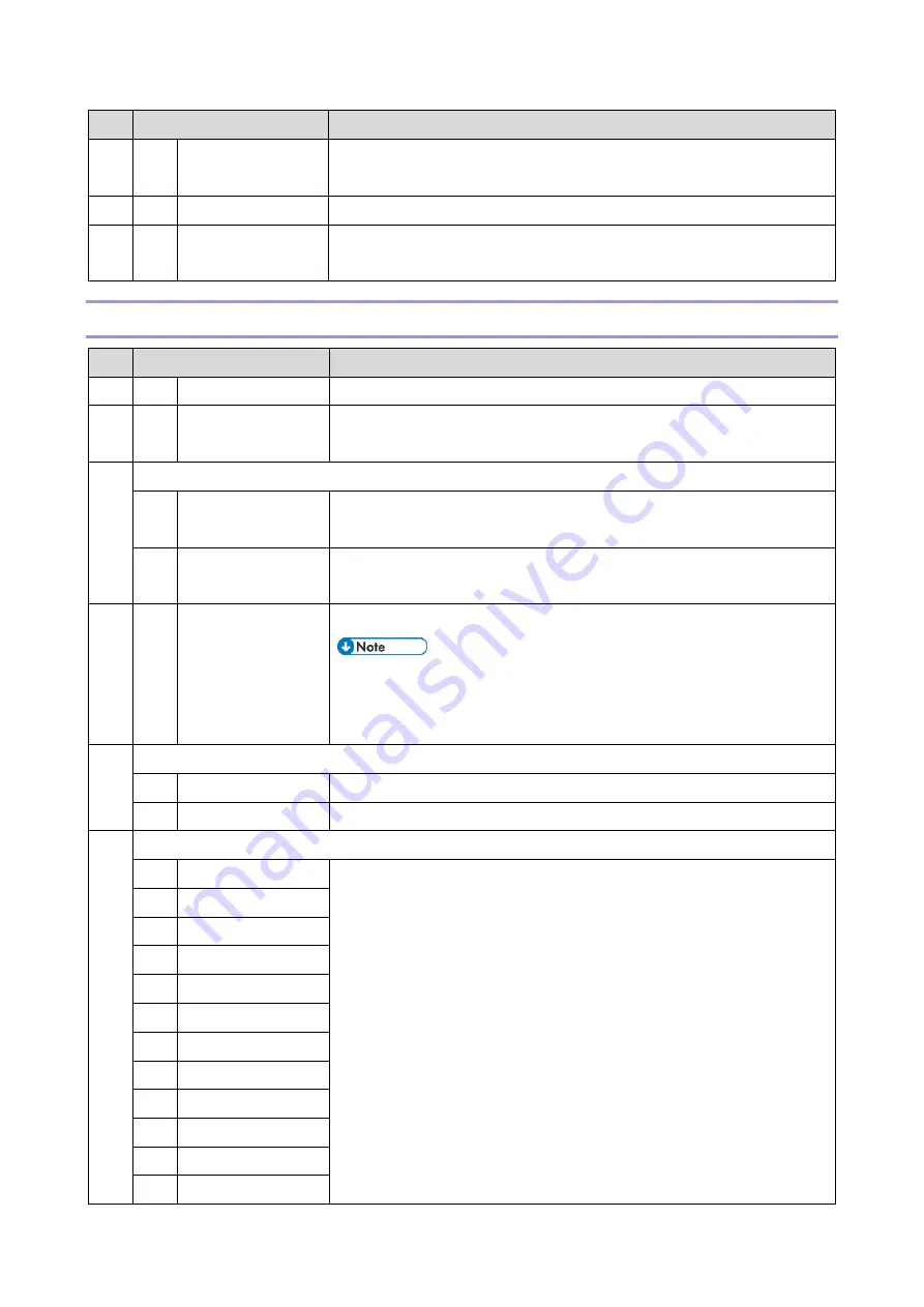
Mode No.
Function
104 001 Factory Setting
Resets the bit switches and user parameters, user data in the SRAM and files in
the SAF memory.
105 001 Reset All Bit Switches Resets all the current bit switch settings.
106 001 Reset Security Bit
Switches
Resets only the security bit switches. If you select automatic output/display for
the user parameter switches, the security settings are initialized.
SP6-XXX (Reports)
6
Mode No.
Function
101 001 System Parameter List Touch the “ON” button to print the system parameter list.
102 001 Service Monitor
Report
Touch the “ON” button to print the service monitor report.
103 G3 Protocol Dump List
002 G3-1 (All
Communications)
Prints the protocol dump list of all communications for the G3-1 line.
003 G3-1
(1 Communication)
Prints the protocol dump list of the last communication for the G3-1 line.
105 001 All Files print out
Prints out all the user files in the SAF memory, including confidential messages.
Do not use this function, unless the customer is having trouble
printing confidential messages or recovering files stored using the
memory lock feature.
106 Journal Print out
001 All Journals
The machine prints all the communication records on the report.
002 Specified Date
The machine prints all communication records after the specified date.
107 Log List Print out
001 All log files
These log print out functions are for designer use only.
002 Printer
003 SC/TRAP Stored
004 Decompression
005 Scanner
006 JOB/SAF
007 Reconstruction
008 JBIG
009 Fax Driver
010 G3CCU
011 Fax Job
012 CCU
Содержание M0A0
Страница 2: ......
Страница 10: ...8 ...
Страница 12: ......
Страница 30: ...2 Installation 18 Destination For printing images For operating NA 8 66 10 8 66 15 EU AP CHN 10 15 ...
Страница 33: ...2 Installation 21 6 Enter the password again 7 Press OK 8 Change the Administrator 1 login password ...
Страница 34: ...2 Installation 22 9 Enter the password 10 Press OK 11 Enter the password again ...
Страница 85: ...2 Installation 73 ...
Страница 127: ...4 Replacement and Adjustment 115 PCDU PCDU 1 Open the front cover A 2 Hold the grip to pull the PCDU A out ...
Страница 189: ...4 Replacement and Adjustment 177 ...
Страница 203: ...5 System Maintenance 191 SP Mode Tables See Appendices ...
Страница 229: ...5 System Maintenance 217 LDAP authorization information ...
Страница 344: ...7 Detailed Descriptions 332 side guides from side to side ...
Страница 358: ...7 Detailed Descriptions 346 ...
Страница 367: ...Latest Release Initial Release August 2016 Copyright c 2016 Ricoh Co Ltd MP 402SPF Machine Code M0A0 Appendices ...
Страница 368: ......
Страница 558: ......
Страница 560: ...2 Software Update Errors 57 Errors That Occur When the Control Panel Downloads Data from the Controller at Startup 62 ...
Страница 574: ...1 Replacement and Adjustment 16 7 LCD A 4 8 Microphone A cushioning 1 ...
Страница 622: ......
Страница 624: ... A Short Edge Feed SEF B Long Edge Feed LEF ...
Страница 626: ......
Страница 632: ...1 Installation 6 ...
Страница 703: ...4 Service Tables 77 0 Off 1 On change occurs such as an optical fiber line 5 7 Not used Do not change the settings ...
Страница 752: ...5 Detailed Section Descriptions 126 Report Sample ...
Страница 758: ...6 Specifications 132 Fax Unit Configuration Component No Remarks FCU 1 Speaker 2 ...
Страница 760: ......
Страница 762: ......
Страница 766: ...1 Detailed Descriptions 4 SW 1 SW 2 SW 3 Paper Size 7 H L H Half Letter SEF 8 H H H Paper cassette is not set ...
Страница 776: ...2 Replacement and Adjustment 14 4 Detach the paper size switch from the bracket A Hook x2 ...


