


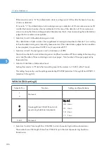


• Selector 7 is applicable to models equipped with ADF units.
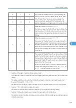
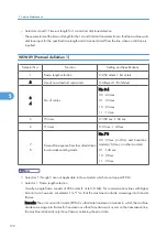
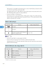
• Selector 2: ITU-T (CCITT) superfine recommendation
If this selector is set to "1," the machine communicates in ITU-T (CCITT) recommended superfine mode
(15.4 lines/mm). If it is set to "0," it communicates in native superfine mode.
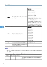
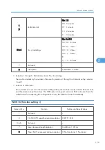
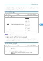
• Selector 7: Max. document length limitation
This selector is used to select the maximum length of a document to be sent.
• Selector 8: "Stop" key pressed during reception
If this selector is set to "1," pressing the "Stop/Exit" key can stop the current receiving operation. The
received data will be lost.
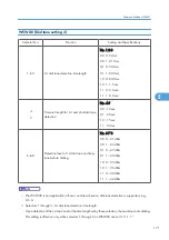
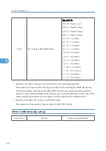
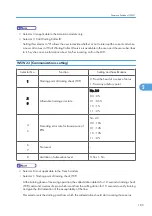
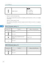
WSW17 (Function setting 2)
Selector No.
Function
Setting and Specifications
1
2
Off-hook alarm
No. 1 2
0 0 : No alarm
0 1 : Always valid
1 X : Valid except when 'call
reservation' is selected.
3
4
Not used.
-
5
Calendar clock type
0: U.S.A. type 1: European type
6
Not used.
-
7
Non-ring reception
0: OFF 1: ON
8
Not used.
-
• Selectors 1 and 2: Off-hook alarm
These selectors activate or deactivate the alarm function which sounds an alarm when the
communication is completed with the handset being off the hook.
• Selector 5: Calendar clock type
If this selector is set to "0" (USA), the MM/DD/YY hh:mm format applies; if it is set to "1" (Europe),
the DD/MM/YY hh:mm format applies: DD is the day, MM is the month, YY is the last two digits of
the year, hh is the hour, and mm is the minute.
5. Service Maintenance
180
5
Содержание HL-F1
Страница 1: ...Model HL F1 Machine Code H558 Field Service Manual 14 May 2010...
Страница 2: ......
Страница 13: ...1 Product Information Specifications See Appendices for the Specifications 11 1...
Страница 15: ...Rear View 12 USB Interface Connector 13 Back Cover 14 AC Power Connector Overview 13 1...
Страница 18: ...Components The equipment consists of the following major components 1 Product Information 16 1...
Страница 22: ...2 Installation 20 2...
Страница 23: ...3 Preventive Maintenance PM Tables There are no PM parts for this machine 21 3...
Страница 24: ...3 Preventive Maintenance 22 3...
Страница 33: ...Disassembly Flowchart Before You Do 31 4...
Страница 34: ...Common Parts Paper Eject Tray 1 Remove the paper eject tray A Drum Toner ASSY 4 Replacement and Adjustment 32 4...
Страница 43: ...4 Remove the separation rubber A ADF plate spring B and front plate spring C x 1 B M3x6 Common Parts 41 4...
Страница 44: ...5 Remove the actuator R A from the panel unit B 4 Replacement and Adjustment 42 4...
Страница 45: ...6 Release the four hooks to remove the panel rear cover A x 3 B M3x8 Common Parts 43 4...
Страница 48: ...11 Remove the rubber key A 4 Replacement and Adjustment 46 4...
Страница 51: ...Top Cover 1 Rear Chute Cover p 34 2 Remove the rear cover stopper A x 1 B M4x12 Common Parts 49 4...
Страница 60: ...22 Remove the CIS A 23 Disconnect the CIS harness A 4 Replacement and Adjustment 58 4...
Страница 61: ...24 Remove the two CIS springs A 25 Remove the LF roller gear A Common Parts 59 4...
Страница 63: ...28 Remove the scanning motor F sub ASSY A x 1 M3x6 Common Parts 61 4...
Страница 101: ...4 Remove the HVPS insulation sheet A 5 Remove the gear plate calking ASSY B x 3 B M4x12 Main Body 99 4...
Страница 106: ...2 Remove the main frame L A x 2 B M4x12 Main Frame R 1 Main Frame L p 103 4 Replacement and Adjustment 104 4...
Страница 107: ...2 Remove the main frame R A x 3 B M4x12 Main Body 105 4...
Страница 110: ...FG harness ASSY 1 Main PCB 2 FG harness ASSY 3 Laser unit 4 Replacement and Adjustment 108 4...
Страница 111: ...Regist sensor PCB ASSY 1 PS PCB unit 2 Regist sensor PCB ASSY 3 Chute Harness Routing 109 4...
Страница 112: ...Fan Motor 60 Unit 1 Fan motor 60 unit 2 Main PCB 4 Replacement and Adjustment 110 4...
Страница 113: ...Toner LED PCB ASSY Fan 40 1 Fan 40 2 Label side 3 Toner LED PCB ASSY 4 PS PCB unit Harness Routing 111 4...
Страница 114: ...Toner Sensor PCB ASSY 1 High voltage PS PCB ASSY 2 Toner sensor PCB ASSY 4 Replacement and Adjustment 112 4...
Страница 120: ...CIS 1 Main PCB 2 CIS 4 Replacement and Adjustment 118 4...
Страница 153: ...7 Select Search for a suitable driver for my device recommended and click Next Firmware Installation 151 5...
Страница 155: ...10 Click Next Firmware Installation 153 5...
Страница 156: ...11 To proceed click Yes 5 Service Maintenance 154 5...
Страница 218: ...Image Defects 6 Troubleshooting 216 6...
Страница 255: ...Model HL F1 Machine Code H558 Appendices 14 May 2010...
Страница 256: ......
Страница 258: ...2...
Страница 296: ...2 Appendix Troubleshooting Guide 40 2...